Type of fusing
The energy storage system includes, among other components, a fusing element as well as two contactors for synchronization of the storage unit and DC link. An SEW-EURODRIVE MOVI-C® controller with a license for a MOVIKIT® PowerMode or EnergyMode software module is required to control these components. The use of these MOVIKIT® software modules is a prerequisite for safe operation of the system. The complete fuse concept is shown in the following figure:
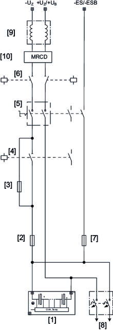
[1] | Energy modules | [6] | Synchronization contactors |
[2] | Main fuse | [7] | Measuring channel fuse |
[3] | Subfuse | [8] | Discharge fuse |
[4] | Bypass contactor | [9] | Choke |
[5] | Disconnector | [10] | Modular residual current device |
In the normal functional range (e.g. 400 V to 800 V), only the main fuse is active. The subfuse is short-circuited by the bypass contactor. The fuse size and the functional voltage range are exactly matched by SEW-EURODRIVE so that in the event of a short circuit, the short-circuit current is sufficient to trip the main fuse. At a certain voltage below the functional voltage range, the bypass contactor is opened and the smaller subfuse becomes active. This also provides adequate protection for the charging and discharging points of the energy storage system. This type of fusing ensures safe tripping in the event of a short circuit over the entire voltage range. These fuses do not offer protection in the event of a thermal overload. In this case, protection is ensured by the selected cable cross sections, power limitations of the devices and design of the entire system.
The fuse concept is defined by SEW-EURODRIVE as part of the project planning process. Only use the fuses configured by SEW-EURODRIVE.
INFORMATION