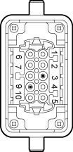
Connection to terminal X_2A of open-end cables with HAN-10E connector
The following table shows the core assignment of cables with the following part numbers:
Part numbers |
|---|
28128524 |
Assembly | |||||||
|---|---|---|---|---|---|---|---|
Open cable end at the motor | Motor connection depending | Assembled connector | |||||
| Without | Three-wire brake (e.g. BE/BZ | Two-wire brake (e.g. BK/BP |
| |||
Core color/ | Marking | Assembly | Description | Signal | Contact | ||
Black | U | Conductor end sleeve | Motor connection, phase U | U | 1 | ||
V | Conductor end sleeve | Motor connection, phase V | V | 2 | |||
W | Conductor end sleeve | Motor connection, phase W | W | 3 | |||
Black | 1 | Conductor end sleeve | ReservedReserved cores must be isolated and fixed in the connection box. | Brake 13 | Brake+ | Brake 13 | 4 |
Black | 2 | Conductor end sleeve | ReservedReserved cores must be isolated and fixed in the connection box. | Brake 14 | ReservedReserved cores must be isolated and fixed in the connection box. | Brake 14 | 6 |
Black | 3 | Conductor end sleeve | ReservedReserved cores must be isolated and fixed in the connection box. | Brake 15 | Brake- | Brake 15 | 5 |
Green/yellow | – | Conductor end sleeve | Protective earth connection | PE | PE | ||
Pink | – | Conductor end sleeve | Temperature sensor+ connection | Temp+ | 9 | ||
Gray | – | Conductor end sleeve | Temperature sensor- connection | Temp - | 10 | ||
– | – | – | – | res. | 7, 8 | ||