Equipotential bonding of the MOVIONE® decentralized inverter
The following figure shows the connection of the equipotential bonding and the PE conductor:
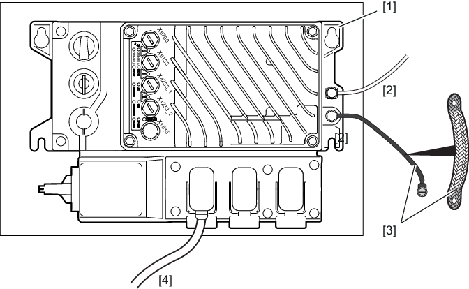
[1] | Flat conductive connection between the MOVIONE® decentralized inverter and the mounting plate, provided that the entire contact surface is electrically conductive (e.g. not painted). |
[2] | Second PE conductor via separate terminals |
[3] | EMC-compliant equipotential bonding, e.g. via grounding strap (HF litz wire). The contact surfaces must be electrically conductive (e.g. unpainted). |
[4] | PE conductor in the supply system cable |
INFORMATION