Gateways, communication modules, and cable routing
Proceed as follows:
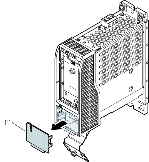
- Remove the cover [1].
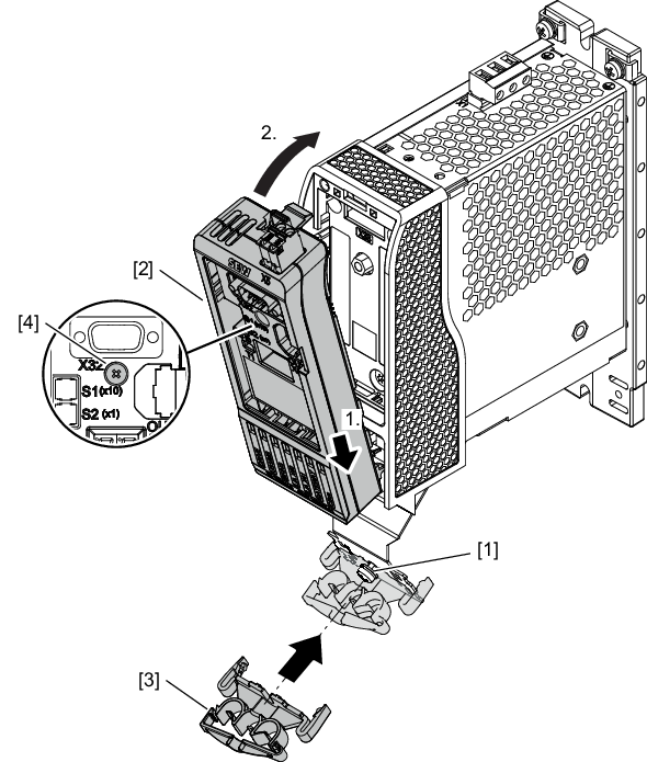
- Install the gateway [2] on the front of the inverter and tighten the retaining screw [4].
- Mount the cable clip [3] on the shield plate as cable routing for the network cables. First, remove the clamping bracket of the shield plate by loosening the screw [1]. The cable clip can then be attached and fastened using the loosened screw.
- The gateway has been installed.
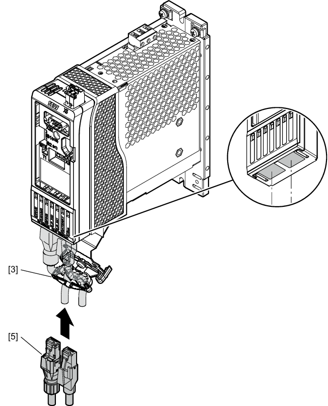
- Connect the network cables.
- For fieldbuses: No particular sequence
- For EtherCAT®/SBusPLUS: X40 (IN) and X40 (OUT)
- To secure the network cables [5], use the cable clip [3].
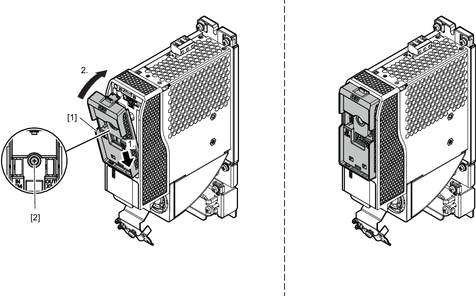
- Install the communication module [1] on the front of the inverter and tighten the retaining screw [2].
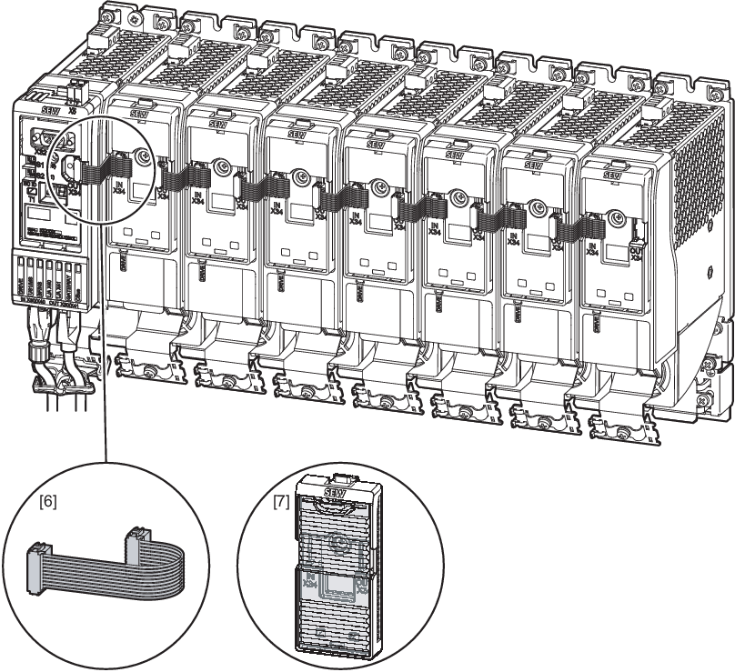
- Connect the gateway to the communication modules with the supplied ribbon cable [6] and route it as follows:
- Reinstall the transparent front cover [7] for all communication modules.