Alternating current/1‑phase/230 V/series connection
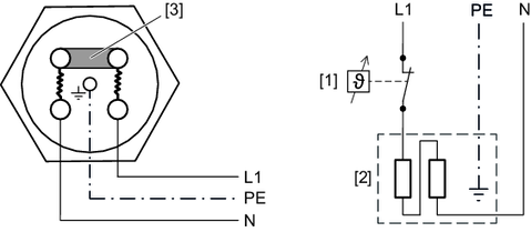
A heating element consists of 2 tubular heating elements. The tubular heating elements of the heater are connected in series. The following figure shows the connection in the connection area of the heating element:
Observe the electrical characteristic data of the control zone. | |
[1] | Thermostat |
[2] | Heating element |
[3] | Jumper |
Cable bushing: 1 x PG11
The following table shows the connected load of the heater that can be installed.
Pinst | Pinst | ||||
|---|---|---|---|---|---|
Gear unit | 1 heating element | 2 heating elements | |||
Size | Design |
| K/h |
| K/h |
X100 | X2K / X2F / X3K | 1 × 0.4 | 6 | 2 × 0.4 | 11 |
X3T / X3F | 1 × 0.3 | 3 | 2 × 0.3 | 7 | |
X110 | X3T / X3F | 1 × 0.3 | 4 | – | – |
X120 | X4F / X3T / X4T | 1 × 0.3 | 3 | 2 × 0.3 | 5 |
X130 | X4F / X3T / X4T | 1 × 0.4 | 3 | – | – |
X140 | X4F / X3T / X4T | 1 × 0.4 | 3 | 2 × 0.4 | 5 |
K/h | = heating capacity (Kelvin/hour) |
Pinst | = Power of the installed heating element |
