Alternating current/1‑phase/230 V/parallel connection/I ≥ 10 A
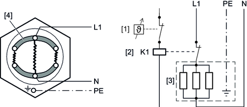
A heating element consists of 3 tubular heating elements. The tubular heating elements of the heater are connected in parallel. The following figure shows the wiring ex works (as viewed into the connection space):
Observe the electrical characteristic data of the control zone. | |
[1] | Thermostat |
[2] | Contactor (not included in the scope of delivery) |
[3] | Heating element |
[4] | Jumper |
Cable bushing: 1 x PG16
The following table shows the connected load of the heater that can be installed:
Pinst | Pinst | ||||
|---|---|---|---|---|---|
Gear unit | 1 heating element | 2 heating elements | |||
Size | Design |
| K/h |
| K/h |
X180 | X2F / X2K / X3K / X3F / X4K | – | – | 2 × 1.6 | 10 |
X200 | X2K | – | – | 2 × 1.5 | 8 |
X2F / X3K / X3F / X4K | – | – | 2 × 1.8 | 8 | |
X4F / X4T | – | – | 2 × 1.3 | 6 | |
X220 | X2K | – | – | 2 × 1.8 | 7 |
X2F / X3F / X4F / X3K / X4K / X3T / X4T | – | – | 2 × 2.2 | 8 | |
X240 | X2K | – | – | 2 × 1.8 | 5 |
X2F / X3F / X4F / X3K / X4K / X3T / X4T | – | – | 2 × 2.2 | 6 | |
X250 | X2F / X3F / X4F / X3K / X4K / X3T / X4T | 1 × 2.6 | 3 | – | – |
K/h | = heating capacity (Kelvin/hour) |
Pinst | = Power of the installed heating element |
