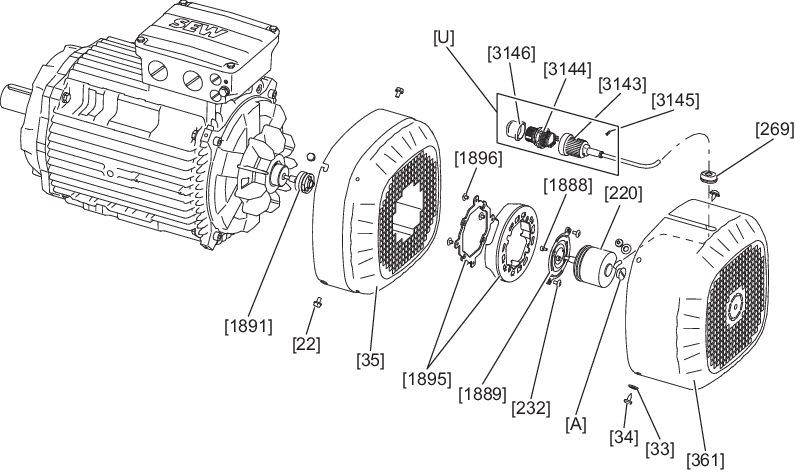
Removing EK8./EK9./AK8./AK9./RK8M – Add-on encoder set with M23 connector directly on KIGA encoder
- For size 71 – 132S with forced cooling fan: Remove the screw [22].
- For size 71 – 132S with forced cooling fan: Remove the screws [34] and the washers [33].
- For size 132M – 355 with forced cooling fan: Remove the screw [22].
- Without forced cooling fan: Remove the screws [34]/[1711].
- Remove the safety cover [361]/[657] or the forced cooling fan [170] from the motor. When doing this, slide the cable grommet [269] out of the recess.
- With forced cooling fan: Remove the signal cable from the cable retainer [1900].
- Unscrew the screws [232].
- Without forced cooling fan: Remove the screws [22].
- Remove the fan guard [35] over the encoder [220]. Guide the M23 connector [U] with the signal cable through the cutout of the fan guard [35].
- For size 132M – 355 with forced cooling fan: Remove the screw [936] or the nut [734], the spacer bushing [934] and the torque bracket [935].
- Unscrew the screw plug [A] of the encoder [220].
- Loosen the central retaining screw of the encoder [220]. Use a tool that is at least 45 mm long for this.
- Loosen the cone connection.
- Remove the encoder [220] from the rotor [1] or from the coupling [233]/[1891].