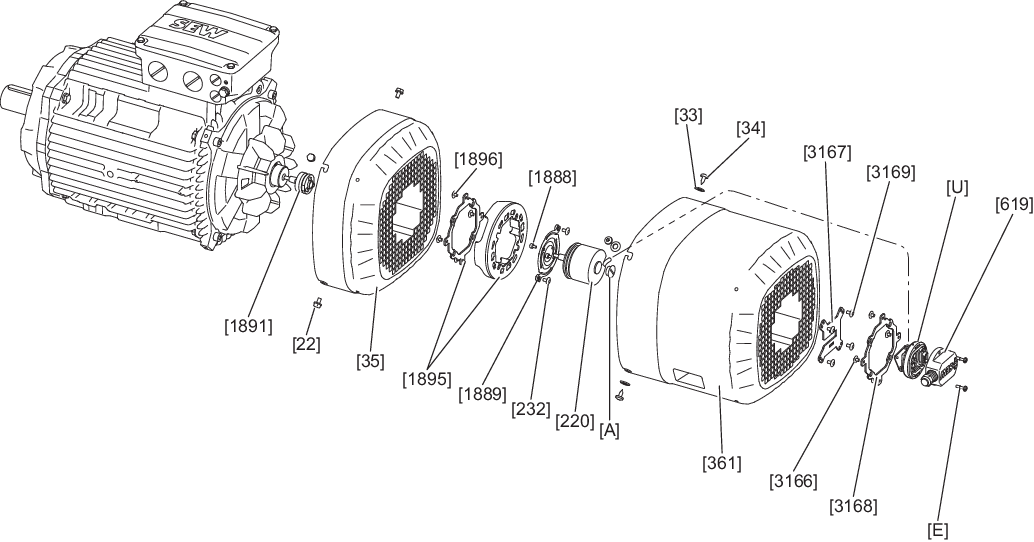
Removing EK8./EK9./AK8./AK9./RK8M – A1GA/A2GA axial add-on encoder set (installation on rear of fan guard)
- Unscrew the screws [E].
- Remove the connection cover [619] from the connection adapter [U].
- Unscrew the screws [3169].
- For size 71 – 280: Unscrew the screws [34].
- For size 315 – 355: Unscrew the screws [1711].
- For size 71 – 280: Remove the safety cover [361] from the fan guard [35].
- For size 315 – 355: Remove the safety cover [657] from the fan guard [35].
- Guide the connection adapter [U] mounted on the support plate [3167] through the opening in the grille of the safety cover [361]/[657].
- Loosen the screws [D] in the lower part [C].
- When doing this, slide the connection adapter [U] out of the recess of the support plate [3167].
- Remove the screws [22].
- Unscrew the screws [232].
- Remove the fan guard [35] over the encoder [220].
- Unscrew the screw plug [A] of the encoder [220].
- Loosen the central retaining screw of the encoder [220]. Use a tool that is at least 45 mm long for this.
- Loosen the cone connection.
- Remove the encoder [220] from the rotor [1] or from the coupling [233]/[1891].