Regenerative power supply module MDR9.B-..
Depiction | Terminal | Connection | Brief description |
|---|---|---|---|
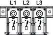
| X1:1 | L1 | Line connection |
X1:2 | L2 | ||
X1:3 | L3 | ||
| PE | PE connection | |
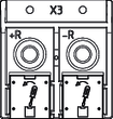
| X3:+R | +R | Braking resistor connection |
X3:-R | -R | ||
| PE | PE connection | |
| X4:+VZ | +VZ | DC link connection |
X4:-VZ | -VZ | ||
| PE | PE connection | |
| X5:24 V | 24 V_in | DC 24 V voltage supply |
X5:GND | GND | ||
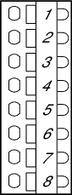
| X7:1 | +TEMP_R | DC 24 V auxiliary voltage output |
X7:2 | -TEMP_R | Sensor input for temperature monitoring of the braking resistor | |
X7:3 | Reserved | – | |
X7:4 | Reserved | – | |
| X12:L1 | L1_S | Line voltage tapping of L1_S from MDF90B filter module |
X12:L2 | L2_S | Line voltage tapping of L2_S from MDF90B filter module | |
X12:L3 | L3_S | Line voltage tapping of L3_S from MDF90B filter module | |
| PE | PE connection | |
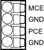
| X13:MCE | MCE | Main Contact Enable (MCE), DC 24 V voltage output for controlling the coupling relay K1 for the line contactor K3 |
X13:GND | GND | Reference potential | |
X13:PCE | PCE | Pre Charge Enable (PCE) If jumper PCE to GND is open, precharge inhibit is activated. The bridge is supplied pre-installed. | |
X13:GND | GND | Reference potential | |
| PE | PE connection | |
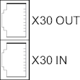
| X30 OUT | System bus | |
X30 IN | |||
| X31 |
| SEW‑EURODRIVE Service interface |
| X20:1 | DI01 | Digital input: Selection of FCB 58 Supply and regenerative modeThe assignment specified here is the factory setting. The inputs and outputs can be programmed as required |
X20:2 | DI02 | Digital input: Fault reset1) | |
X20:3 | DI03 | Digital input: Selection of FCB 53 Hold precharge1) | |
X20:4 | DI04 | Digital input: Inhibit energy recovery function1) | |
X20:5 | DI05 | Digital input: Inhibit step-up function1) | |
X20:6 | DI06 | Digital input: no function | |
X20:7 | GND | Reference potential | |
X20:8 | 24V_out | DC 24 V voltage output | |
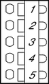
| X21:1 | DO00 | Digital output: DC link ready1) |
X21:2 | DO01 | Digital output: Precharging active1) | |
X21:3 | DO02 | Digital output: No function | |
X21:4 | DO03 | Digital output: Fault1) | |
X21:5 | GND | Reference potential |