Parameter group 70. Operating mode 1/2
This parameter is used to set the basic operating mode of the inverter. They are set on the keypad.
VFC / V/f characteristic curve:
Default setting for asynchronous motors. Suitable for general applications, such as conveyor belts, trolleys, and hoists with counterweight.
VFC & hoist:
The hoist function automatically provides all functions necessary for operating an unbalanced hoist. For safety reasons, make sure to activate monitoring functions that prevent the drive from starting. Monitoring functions:
- Monitoring the output current during the premagnetization phase
- Avoiding sag when the brake is released
The unit detects the following incorrect configurations and displays them with the following faults:
- 2 or 3-phase motor phase interruption: Error F82 output open
- Premagnetization time too short or incorrect motor/inverter combination: Fault F81 start condition
- Motor phase failure due to active speed monitoring P500/502: Fault F08 speed monitoring
NOTICE:
- Control must be implemented in such a way that the direction of rotation of the drive can only be changed when it is at standstill.
- A 1-phase motor phase failure cannot always be detected reliably.
- SEW-EURODRIVE strongly recommends that you set the speed monitoring time to a small value.
- Requirement for correct performance of the hoist function: The motor brake is controlled by the inverter.
- Speed monitoring is set by changing parameters P501 / P503. The sagging of hoists cannot be avoided safely if the delay time is set to an excessively high value.
VFC & DC braking / V/f characteristic curve & DC braking:
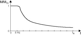
DC braking means the asynchronous motor brakes by using current injection. The motor brakes without a braking resistor on the inverter. The following figure shows the braking torque profile when the braking current is the same as the rated motor current.

During braking, the inverter injects a constant current with a rotating field frequency of 5 Hz. The braking torque = "0" at standstill. At a low speed, the braking torque is high, at higher speeds, the braking torque decreases. The braking time and consequently the duration of the braking current depends on the load connected to the motor. DC braking stops at a rotating-field frequency of the motor of 5 Hz. The motor stops along the stop ramp. Rated motor current is used for the current injection. In all cases, the inverter limits the current to max. 125% IN. See Brake function for brake control.
NOTICE:
With DC braking, guided stops are not possible and certain ramp values cannot be observed. The main purpose of DC braking is to drastically reduce the time the motors need for coasting to a halt.
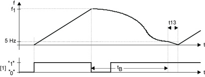
The following diagram shows the braking profile.

n1 = Setpoint speed
[1] = Enable
t13 = Stop ramp
tB = Braking phase
VFC & flying start function:
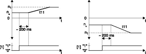
The flying start function lets you synchronize the inverter to a motor that is already in operation. This function is used in particular with drives that are not braked actively, run on for a long time or are turned by a flowing medium, e.g. pumps and fans. The maximum flying start time is approx. 200 ms.
P320 automatic adjustment is deactivated in "Flying start" mode. It is important that the IxR value P322 (stator resistance) is set correctly to ensure that the flying start function is performed properly.
Startup of an SEW motor: The IxR value is set for an SEW motor at operating temperature. This value has to be reduced if flying start takes place with a cold motor.
The IxR value is measured at startup when a non-SEW motor is started up with MOVITOOLS® MotionStudio.

n1 = Setpoint speed
nM = Motor speed
[1] = Enable
The flying start function does not function if an output filter is connected to the inverter.
NOTICE:
Do not use the flying start function for hoist applications.


