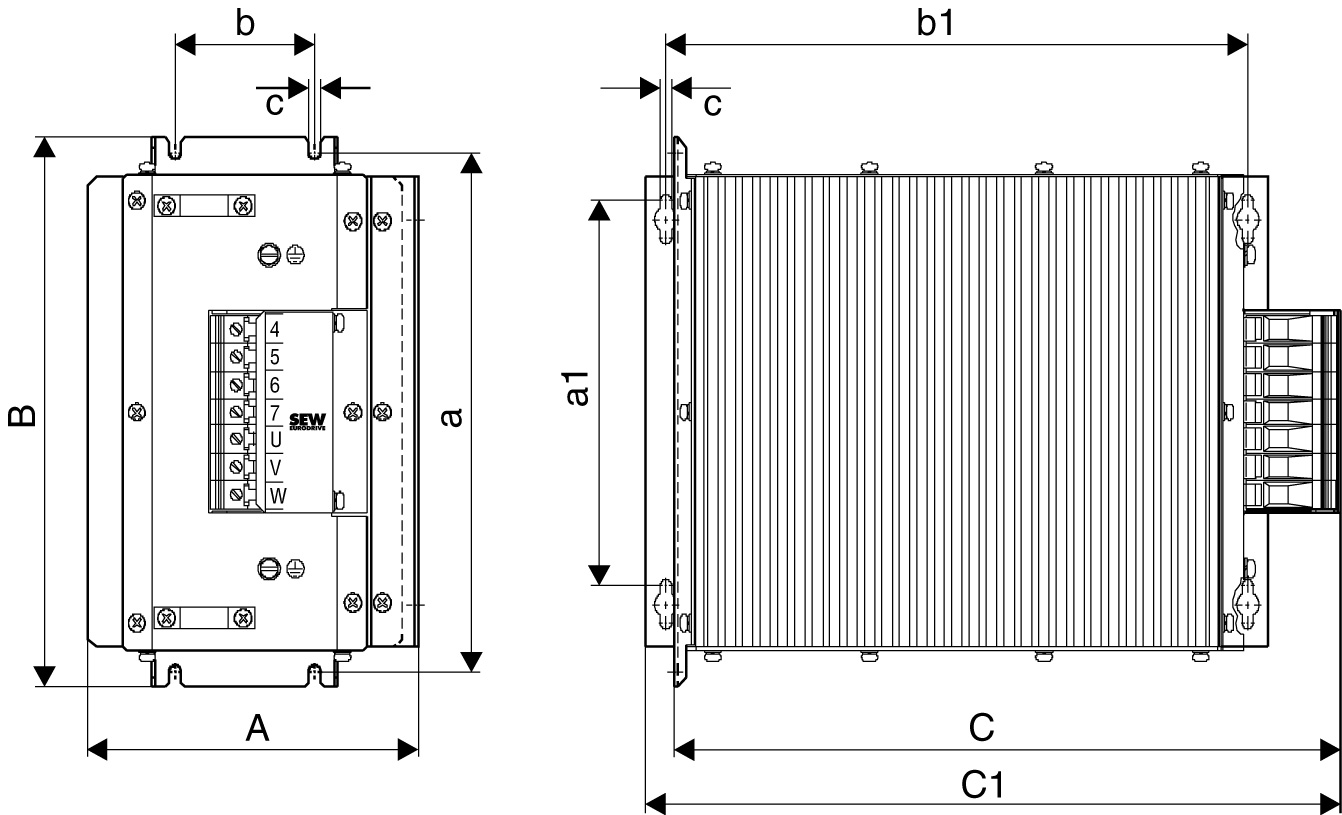
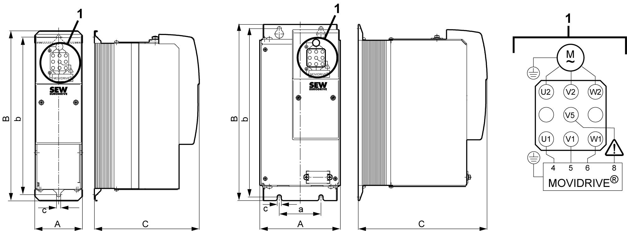
Dimension drawings of HF...-403 output filters
The following figure shows the mechanical dimensions in mm (in):

Type | Main dimensions mm (in) | Mounting dimensions mm (in) | Hole dimension mm (in) | Ventilation clearances mm (in) | |||||||
|---|---|---|---|---|---|---|---|---|---|---|---|
Standard installation | Horizontal mounting position | ||||||||||
A | B | C/C1 | a | b | a1 | a2 | c | On the side | Top | Bottom | |
HF023-403 | 145 (5.71) | 284 (11.2) | 365/390 (14.4/15.4) | 268 (10.6) | 60 (2.4) | 210 (8.27) | 334 (13.1) | 6.5 (0.26) | 30 (1.2) each | 150 (5.91) | 150 (5.91) |
HF033-403 | |||||||||||
HF047-403 | 190 (7.48) | 300 (11.8) | 385/400 (15.2/15.7) | 284 (11.2) | 80 (3.1) | ||||||

The ring cable lug must be attached directly to the copper clip. Only the mounting position shown in the dimension drawing is permitted. |
Output filter type | Main dimensions mm (in) | Mounting dimensions mm (in) | Hole dimension mm (in) | Ventilation clearances mm (in) | ||||||
|---|---|---|---|---|---|---|---|---|---|---|
A | B | C | a | b | c | d | On the side | Top | Bottom | |
HF180-403 | 480 (18.9) | 260 (10.2) | 510 (20.1) | 430 (16.9) | 180 (7.1) | 18 x 13 (0.71 x 0.51) | 11 (0.43) | 192 each (7.6) | 510 (20.1) | 510 (20.1) |
