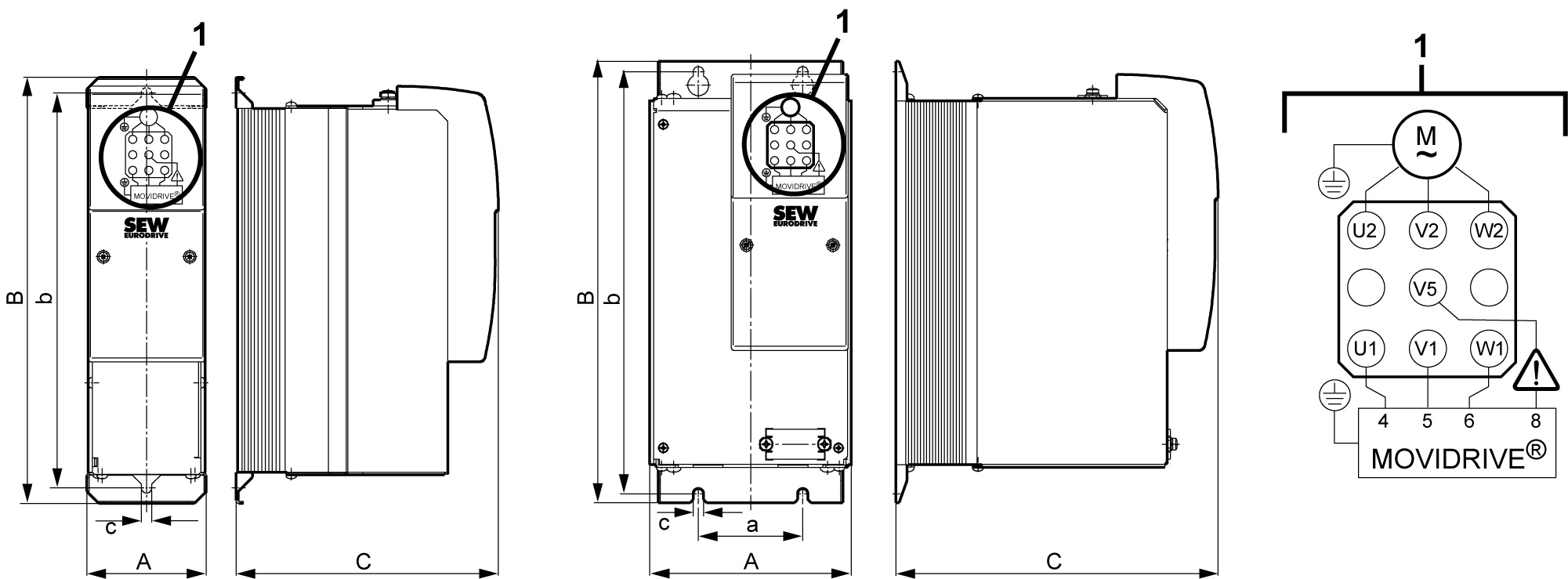
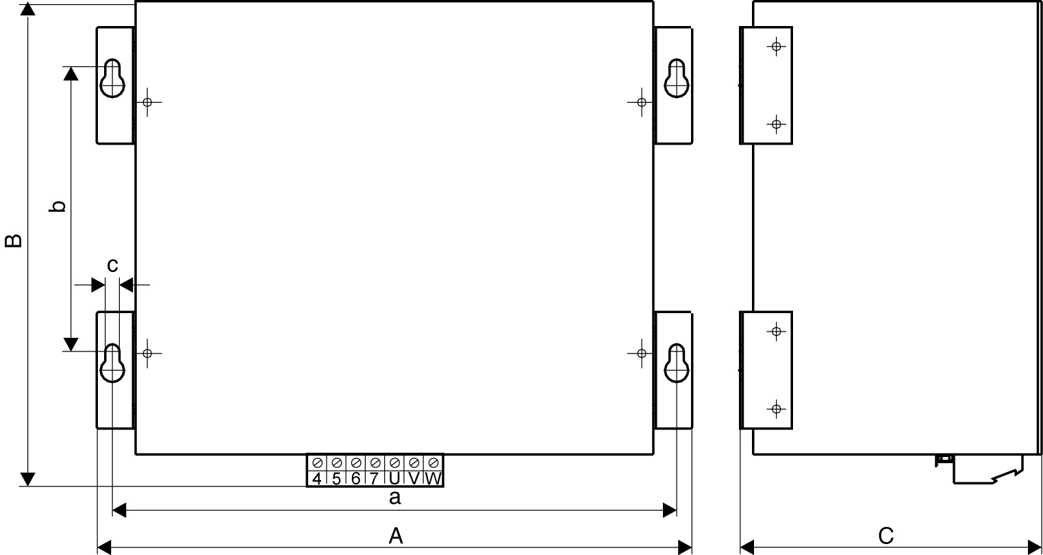
Dimension drawings of HF...-503 output filters
The following figures show the mechanical dimensions in mm (in).
HF008/015/022/030-503 | HF040/055/075-503 |

Only the mounting position shown in the dimension drawing is permitted. |
Output filter type | Main dimensions in mm | Mounting dimensions mm | Hole dimension mm | Ventilation clearancesThere is no need for clearance at the sides. You can line up the devices next to one another. | ||||
|---|---|---|---|---|---|---|---|---|
A | B | C | a | b | c | Top | Bottom | |
HF008/015/022/030-503 | 80 | 286 | 176 | – | 265 | 7 | 100 | 100 |
HF040/055/075-503 | 135 | 296 | 216 | 70 | 283 | |||
HF450-503 |

Only the mounting position shown in the dimension drawing is permitted. |
Output filter type | Main dimensions in mm | Mounting dimensions mm | Hole dimension mm | Ventilation clearances mm | ||||
|---|---|---|---|---|---|---|---|---|
A | B | C | a | b | c | Top | Bottom | |
HF450-503 | 465 | 385 | 240 | 436 | 220 | 8.5 | 100 | 100 |
