Configuring double devices
A double device allows:
- 8 data bits to be used instead of 4 data bits
- parameters to be accessed via CTT2 services
Proceed as follows:
- The device type and device profile are set via DIP switches on the inverter (see Setting the device type with DIP switches. Note that changing the DIP switch position will also change the device address.
- The inverter is supplied with line voltage and/or DC 24 V backup voltage.
- The inverter is addressed (see Setting the inverter address).
- You have added the AS‑Interface master from Bihl+Wiedemann to the TIA Portal project.
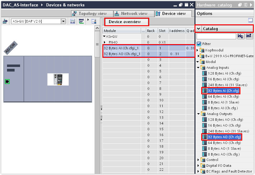
- From the hardware catalog, insert an analog module for the input data and an analog module for the output data into the slots of the AS-Interface master for each double device.
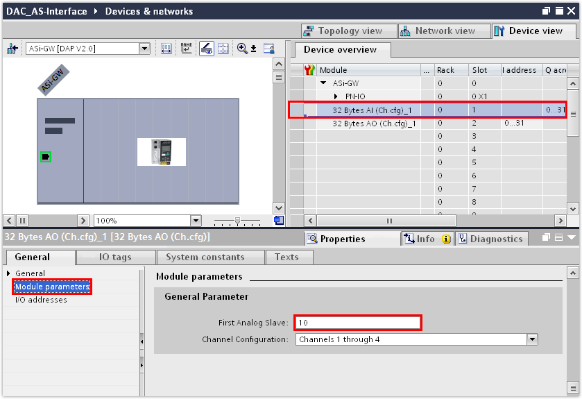
- In the inspector window (lower editor section), enter the device address of the device in the "AS‑Interface" group:
- The device address has been set to 10 in this example.
- Assign a PROFINET device name to the AS-Interface master (PROFINET device) and enter its IP address parameters.
- Switch to the control panel of the master or to the web server function. Start up the AS‑Interface configuration by first checking the status of the current configuration using the "config error LED" and then executing the "Quick Setup" function if necessary. For further information, refer to the documentation supplied by Bihl+Wiedemann.
- Save the TIA Portal project.
- Compile the TIA Portal project and load the project to the PLC.
- To check the settings that have been transferred from the TIA Portal project, switch to the MOVISUITE® project.
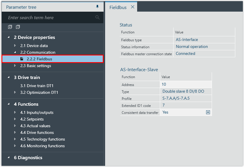
- Check the device address, device type and device profile under [Device properties] > [Communication] > [Fieldbus].
- In this example, the following device parameters have been transferred from the TIA Portal project:
INFORMATION

The acyclic parameter bits of the B device with the S.7.A.5 profile are not supported by SEW‑EURODRIVE. Access to the parameter bits of the A device and to the inverter parameters of the B device by CTT2 services is enabled via a command interface module.
For further information, refer to the documentation of the TIA Portal engineering tool.
INFORMATION
To ensure that the device name of the inverter is compliant both with PROFINET and IEC61131, SEW‑EURODRIVE recommends using a name that starts with a letter and does not contain any spaces or control characters (hyphen, underscore, period, colon, comma, slash, backslash).
When the MOVISUITE® project is imported into TIA Portal, TIA Portal converts the name of the inverter according to an internal algorithm. A name according to the defined naming conventions ensures that the inverter appears under the same name in the various tools.
If a name according to the naming conventions is not possible, select a PROFINET‑compliant name. In this case, IEC61131 compliance is automatically ensured by MOVISUITE®.
Parameter | Value |
|---|---|
Address | 10 |
Type | Double device 8 DI/8 DO |
Profile | S‑7.A.A/S‑7.A.5 |
