Determining the parameter index in MOVISUITE®
In order to be able to access the drive parameters of the decentralized inverter with CTT2 services, the index and subindex of the parameter must be known. These can be determined in the MOVISUITE® engineering tool.
Proceed as follows:
- A MOVISUITE® project with a decentralized inverter has been created.
- Launch the MOVISUITE® project and open the configuration of the inverter.
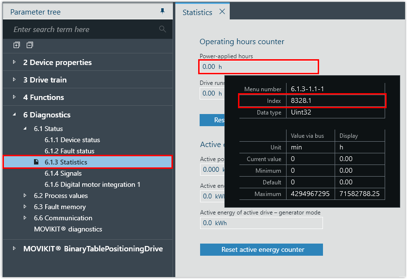
- Hover the cursor over a parameter.
- The parameter properties are displayed.
- In this example, the index and subindex of the
Einschaltstundenparameter are determined.
Tooltip element | Description |
|---|---|
Menu | Unique menu number in MOVISUITE® |
Index | Index.Subindex offset, bit Offset optional – If an offset is not displayed, the offset is 0. Bit mask optional – If the parameter contains multiple values, the bit mask is applied to determine the desired value. |
Data typeFor the BitField or range of values data types, individual bits or values can be defined in the firmware as "Reserved" or "Invalid". In the case of a write access with invalid values, the corresponding error is returned via the Response message. To prevent this, only the values displayed in the tooltip are allowed to be used. | The following data types are possible:
|
SI unit/user unit | Unit of the parameter The user unit is a unit of measurement defined by the user (e.g. speed values). |
Read access | Value: OBSERVER Access to the available device functions that are visible in the parameter tree may be restricted by the parameter setting mode, parameter lock, drive states, energy saving mode, etc. Read access is also possible in restricted inverter states. |
Write access | The following values are possible:
|
Value |
|
Minimum | Smallest permitted value |
Standard | Default value in the firmware |
Maximum | Largest permitted value |
- Note the index and subindex of the parameter.
- In this example, the parameter has the Index.Subindex: 8328.1
- Convert the decimal representation of the index and subindex to hexadecimal representation.
- In this example, the hexadecimal representation of the Index.Subindex is: 0x2088.0x01
