Adjustment with adjust function in StartMode "CONTINUE_SYNCHRONIZED"
As explained in chapter Synchronization mechanism with synchronous point, with the StartMode "CONTINUE_SYNCHRONIZED" the suspension point of the straight line, with which the position reference between master and slave axis is defined uniquely, results from the internally stored values of the last master position and the last slave position.
The user can control these two internal reference positions. For this purpose, the "gearing" operating mode must be deactivated by setting the ProfileGeneration.Gearing.in.xActivate input variable to "FALSE".
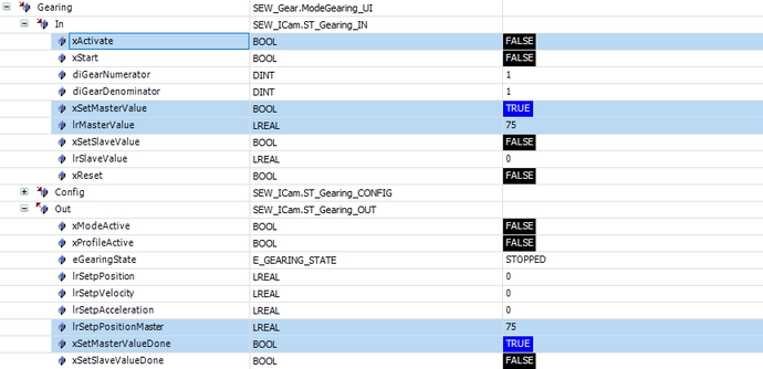
To set the master reference position, the desired value is set via the ProfileGeneration.Gearing.In.lrMasterValue variable and then the ProfileGeneration.In.xSetMasterValue variable is set to "TRUE". If the ProfileGeneration.Gearing.Out.xSetMasterValueDone output variable returns the value "TRUE", the desired master reference position has been applied. The set value is mirrored back via ProfileGeneration.Gearing.Out.lrSetpPositionMaster.
Interface in the IEC Editor

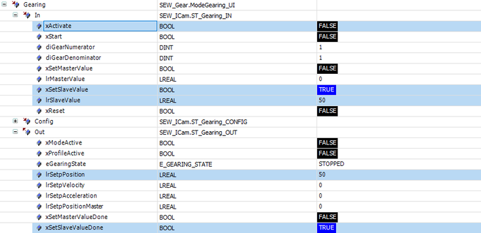
To set the slave reference position, the desired value is set via the ProfileGeneration.Gearing.In.lrSlaveValue variable and then the ProfileGeneration.In.xSetSlaveValue variable is set to "TRUE". If the ProfileGeneration.Gearing.Out.xSetSlaveValueDone output variable returns the value "TRUE", the desired slave reference position has been applied. The set value is mirrored back via ProfileGeneration.Gearing.Out.lrSetpPosition.
Interface in the IEC Editor

After the user has set the reference positions in this way, the "gearing" operating mode can be activated in the CONTINUE_SYNCHRONIZED StartMode by setting the ProfileGeneration.Gearing.In.xActivate variable to "TRUE".
The following actions are performed with the rising edge:
- The difference between the current master position and the set master reference position is calculated.
- This difference is offset against the numerator/denominator factors set via the variables ProfileGeneration.Gearing.In.diGearNumerator or ProfileGeneration.Gearing.In.diGearDenominator.
- The deviation scaled in this way is added to the set slave reference position and results in the slave setpoint position.
- The difference between the current slave position and the calculated slave setpoint position is calculated.
- This position is set as the distance to be corrected during adjustment.
- The current master position and the slave setpoint position calculated from it are applied as new reference positions.
Example
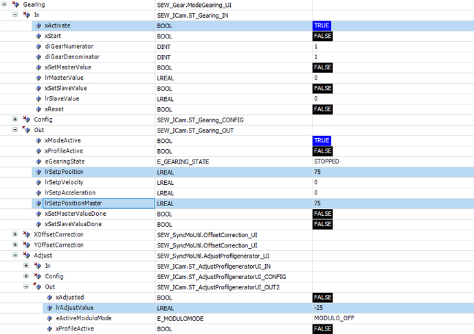
The current master position is 75.0 mm and the current slave position is 50.0 mm. The scaling factors are set to 1. The zero position of both axes is set as the reference positions. The "gearing" operating mode is activated. This results in the following values:
- Deviation of the master position from the reference position: 75.0 mm
- Scaled deviation: 75.0 x 1 / 1 = 75.0
- Scaled deviation plus slave reference position = 75.0 mm = slave setpoint position
- Difference of the current slave position from the slave setpoint position = -25 mm
- The adjust function must move the slave axis from -25.0 mm to 0.0 mm.
Interface in the IEC Editor

INFORMATION

