Additional process values
The following application example shows how additional process values of the inverter can be configured and evaluated in the IEC project. In the example, the digital inputs of the I/O option card and the active power (as a double word) are transferred.
- In the configuration menu "Basic settings" under "Functions used", open the configuration of the software module and activate the function "Additional process values of the inverter".
- Further setting options for configuring the additional process values of the inverter are displayed.
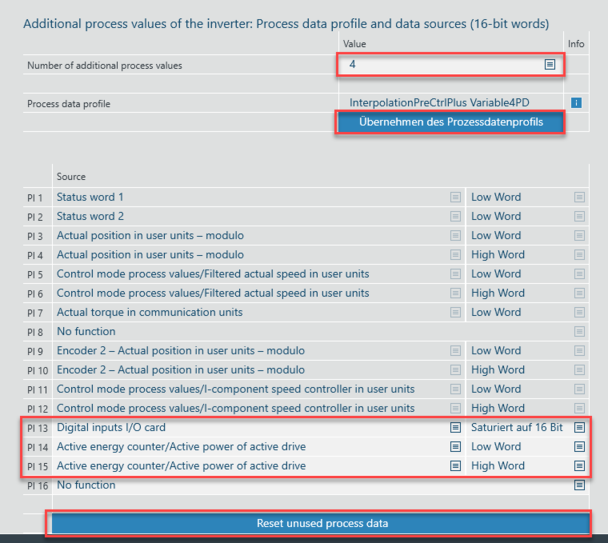
- Use the "Number of additional process values" setting option to specify how many additional process values are to be transferred (in the example: 4).
- The following table provides an overview of possible combinations with other functions.
- The process data profile matching the selected function is displayed in the "Process data profile" setting option.
Selected function | Number of available | Required |
|---|---|---|
Touchprobe | 0 | InterpolationFlexFull |
Position controller | 4 | InterpolationPreCtrlPlus |
Usage of the send object | 4 | InterpolationPreCtrlPlus |
No other functions | 8 | InterpolationPreCtrl |
|
- To apply the configured additional process values, click [Apply process data profile].
- The available process data words can now be edited in the overview of process data words (in the example: PI 13-15).
- To reset the process data assignment to the factory settings, click [Reset unused process data].
- Unused process data words are assigned "No function".
- Configure the process data words as required. The following assignment is made in the example:
- PI 13 – Digital inputs I/O card – saturated to 16 bits
- PI 14 – Active energy counter/active power of active drive – low word
- PI 15 - Active energy counter/active power of active drive – high word
- Update the IEC project. See also Generating an IEC project.
- The updated IEC project is displayed in the IEC Editor.
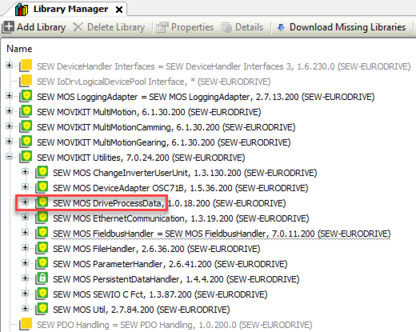
- Open the library manager and add the "MOVIKIT Utilities" library via the path
Application/SEW-EURODRIVE/MOVIKIT. - The function blocks of the "MOVIKIT Utilities" library are available in the IEC project.
- The "SEW MOS DriveProcessData" library included in the "MOVIKIT Utilities" library contains the function block "AdditionalPD" for reading/writing the additional process values.
INFORMATION

You can also transfer process values from the MOVI-C® CONTROLLER to the inverter. The same unassigned PD numbers apply as for the PI data. You can set the PO data in the configuration in the drive (e.g. for the digital outputs of the I/O option card in the "Inputs/outputs IO card" menu). Bear in mind that counting of PO data starts at 0.
|
|
Scope | Name | Type | Description |
|---|---|---|---|
Input | xEnable | BOOL | Activate transfer |
usiPdNum | USINT | Process data number | |
wWritedata | WORD | Process value to be written | |
eMode | SEW_MK_Util.E_Mode.Read SEW_MK_Util.E_Mode.Write | Read or write | |
Axis | SEW_IBas.IQueryInterfaceSEW | Reference to an axis of the type "MultiMotion" | |
Output | xValid | BOOL | Data are valid |
xError | BOOL | Error | |
eError | SEW_MK_Util.E_ERROR | Error number | |
wReadData | WORD | Process value read |
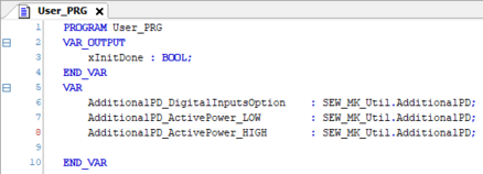
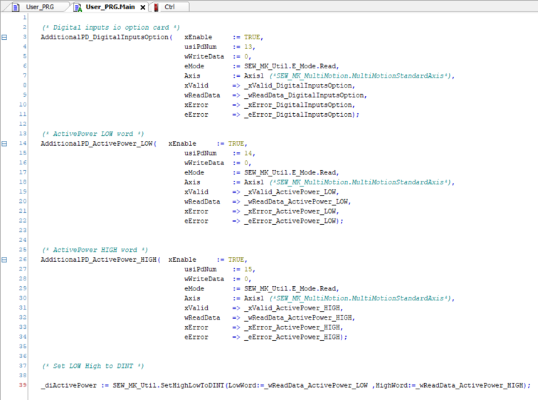
- Create an instance of the "AdditionalPD" function block in User_PRG for each process value to be read or written and call the function blocks in User_PRG.Main. Information: Using the function SetHighLowToDINT that is also included in the library, you can easily convert low word and high word into a DINT.


