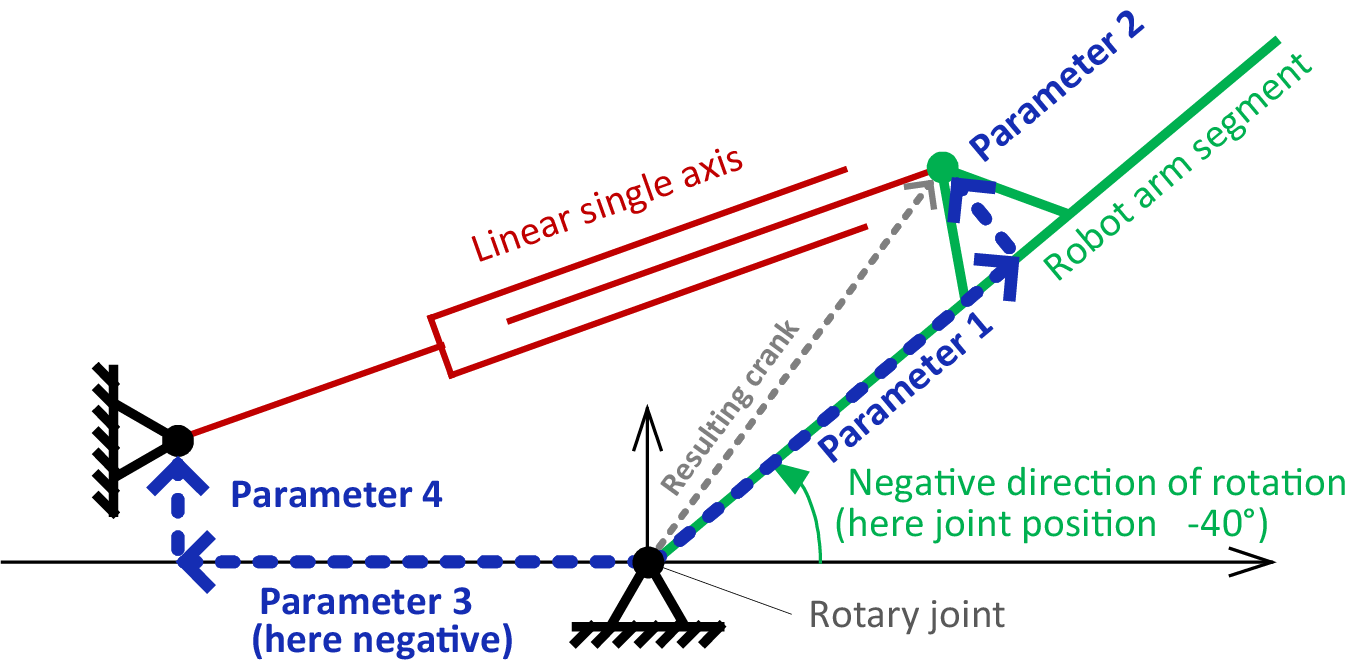
Linear axis to rotary joint
With this type of crank, the motion of a linear single axis is transferred to the motion of a rotary joint axis.

Example:
In the example, parameters 1, 2, and 4 are positive, parameter 3 is negative. As parameter 2 is positive, the linear single axis in the figure moves above the rotary joint axis. If parameter 2 were negative, the linear single axis would move below the rotary joint axis. In the example, the robot arm has the joint axis value -40 °. For example, if the robot arm is pointing horizontally to the right, it has the joint axis value 0°. For example, if the robot arm is pointing vertically upwards, it has the joint axis value -90°. The linear single axis would therefore have to be lengthened to approach 0° compared to the position in the figure, and shortened to approach -90°.
Parameterization
Parameter | Description |
|---|---|
Cranks | |
Index | Index of single axis and joint axis between which the crank operates (the value 1 must be entered for the 1st axis). |
Parameter 1 | Offset from the rotary joint axis along the robot arm that is turned around the rotary joint axis to the pivot joint between linear single axis and robot arm |
Parameter 2 | Additional offset vertically to the robot arm and at the level of movement of the robot arm to the pivot joint between linear single axis and robot arm. The linear single axis moves on one side of the rotary joint axis or on its other side depending on the sign of parameter 2. |
Parameter 3 | Offset starting from the rotary joint axis along the axis of the robot arm at joint axis value 0° to the pivot joint between base and linear single axis (parameter 3 < 0) |
Parameter 4 | Additional offset vertically to the axis of parameter 3 and at the level of movement of the robot arm to the pivot joint between base and linear single axis. |
Parameters 5..8 | Not used |
