Integrating I/O image of fieldbus option in IEC program
In order to monitor the process data transfer in the IEC editor, an I/O image of the fieldbus option must be integrated in the IEC program. This means:
- A variable for the process data exchange is added to the IEC program that runs on the MOVI‑C® CONTROLLER as standard.
- The variable is linked with the input and output channels of the MOVI‑C® CONTROLLER.
- The task configuration is assigned. The task configuration defines which IEC program is activated by which task with which settings.
- The IEC program is loaded on the memory card of the MOVI‑C® CONTROLLER. This way, the boot project is updated.
Proceed as follows:
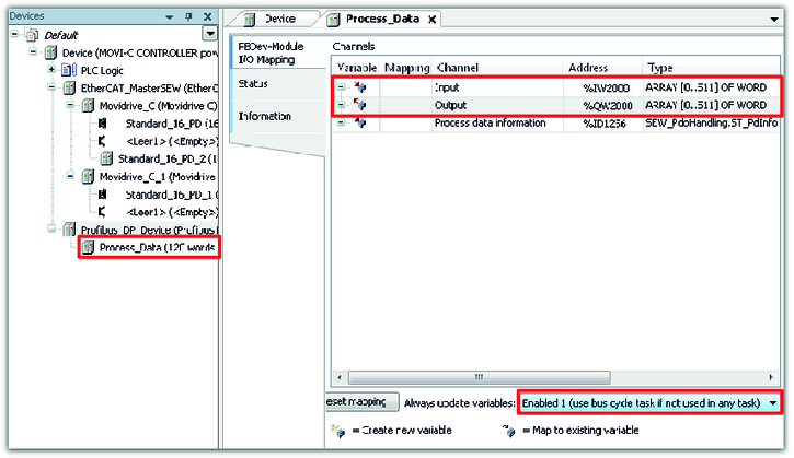
- Check the address of the input and output channels of the MOVI‑C® CONTROLLER. Double-click on the process data of the PROFIBUS device in the device tree and read the assigned addresses of the input and output channels from the "Address" column.
- In this example, the input and output channels have the addresses "%IW2000" and "QW2000".
- Select the setting "Enable 1" from the "Always update variables" drop-down list. This way it is ensured that all values of the declared variable are displayed if communication was established successfully.
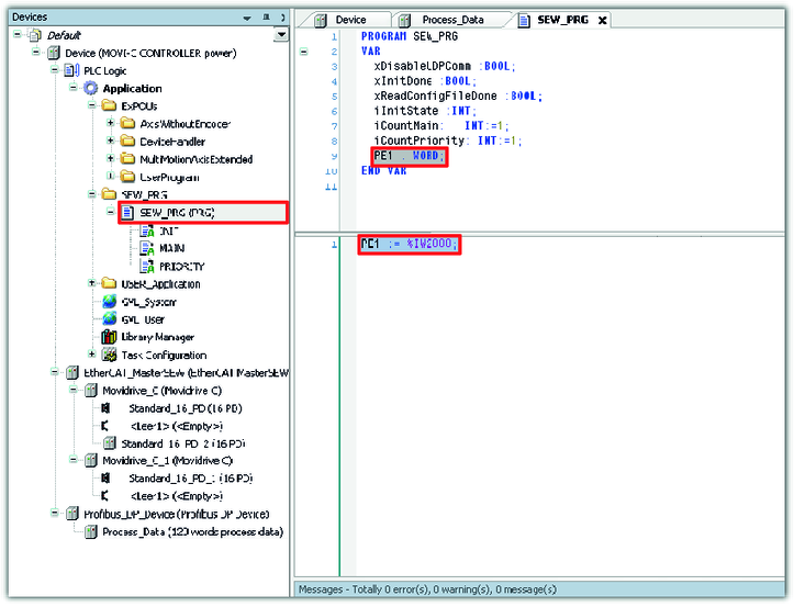
- Double-click on the IEC program "SEW_PRG (PRG)" in the device tree. Declare a variable with which you access the process input data words of the MOVI‑C® CONTROLLER from the IEC program. In the lower window section, enter the variable value in program code.
- In this example, the variable "PE1" is declared. The variable value "%IW2000" defines the address of the input channel. This way, the variable of the IEC program is linked to the input channel of the MOVI‑C® CONTROLLER.
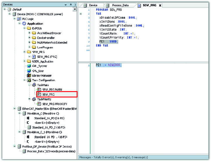
- Add the changed application program to the task configuration using the drag-and-drop function.
- Log into the network and start the IEC editor project.