Integrating and configuring the fieldbus option in the IEC program of the MOVI‑C® CONTROLLER
Proceed as follows:
- Start the IEC editor.
- The boot project of the CFast memory card of the MOVI‑C® CONTROLLER is loaded automatically.
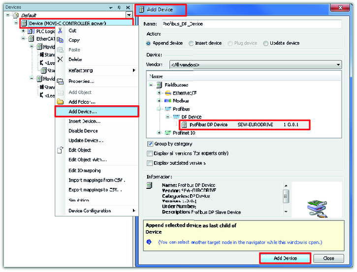
- Open the context menu of the MOVI‑C® CONTROLLER (device) by right-clicking and select the required PROFIBUS device from the device list in the "Add device" window.
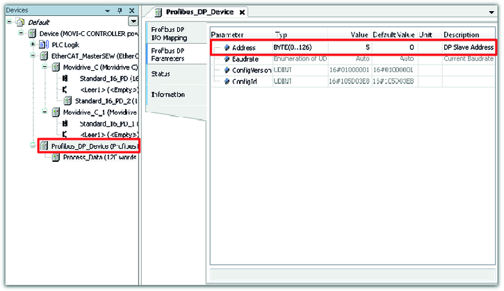
- Double-click the PROFIBUS device. Enter the PROFIBUS address in the "PROFIBUS DP parameter" tab.
- In this example, the PROFIBUS address is 5.
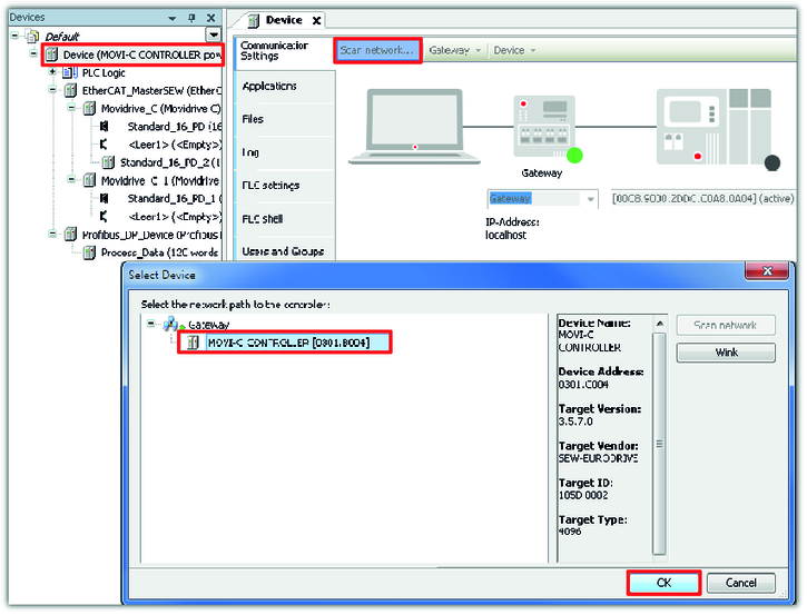
- To establish a connection from the IEC editor project to the MOVI‑C® CONTROLLER, double-click on the MOVI‑C® CONTROLLER (device) in the device tree and scan the network. Add the found device.
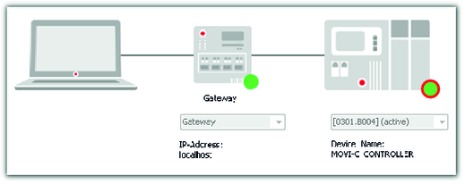
- If the connection is established, the LED of the MOVI‑C® CONTROLLER lights up green.
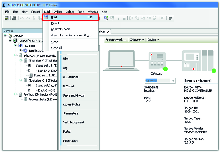
- Build the IEC program in the machine code of the MOVI‑C® CONTROLLER.
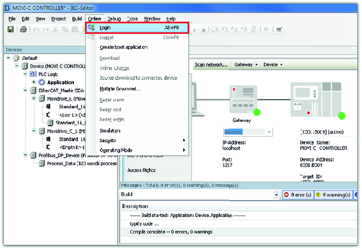
- If the build of the IEC program was successful, the program can be transferred to the MOVI‑C® CONTROLLER. For this purpose, log on to the network.
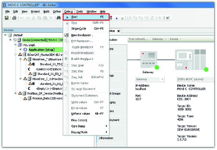
- Start the IEC program.
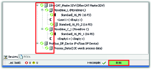
- The MOVI‑C® CONTROLLER starts. The message "RUN" is displayed in the status bar of the IEC editor.
- The devices in the device tree get a green circle. The green circle indicates fault-free function of the fieldbus option but does not indicate the state of communication between MOVI‑C® CONTROLLER and PLC.
- The MOVI‑C® CONTROLLER can only be integrated in a PROFIBUS network.
