Preparing the control cabinet back panel
Proceed as follows:
- Drill the holes according to the following drilling diagram.
- Cut the internal thread in the holes according to the screw size used.
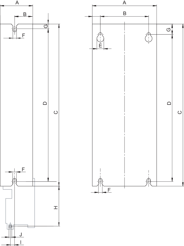
Hole pattern 1 | Hole pattern 2 |
Inverter | Dimensions of the device base plate in mm | Drilling diagram | |||||||||
|---|---|---|---|---|---|---|---|---|---|---|---|
A | B | C | D | E | F | G | I | J | H | ||
Size 0S | 80 | 40 | 220 | 200 (min. 196) | 12 | 6 | 10 | 5.5 | 8 | 78 | 1 |
Size 0L | 80 | 40 | 309 | 288 (min. 284.5) | 12 | 6 | 10 | 5.5 | 8 | 78 | |
Size 3 | 105 | 80 | 350 | 325 | 12 | 6 | 18 | – | – | – | 2 |
Size 4 | 135 | 80 | 350 | 325 | 12 | 6 | 18 | – | – | – | |
Size 5 | 196 | 160 | 471 | 440 | 13 | 7 | 18 | – | – | – | |
Size 6 | 240 | 200 | 544 | 510 | 13 | 7 | 18 | – | – | – | |
Size 7 | 320 | 220 | 990 | 950 | 23 | 11 | 25 | – | – | – | |
Size 8 | 518 | 450 | 990 | 950 | 23 | 11 | 25 | – | – | – | |
