Assignment of terminal X2_B with MMF..DI.. design
For motors without digital interface (MOVILINK® DDI interface)
Terminal | No. | Marking | Connection | |
|---|---|---|---|---|
Brake control /B | /BES brake control | |||
X2_B
For MMF...DI design
For motors | D | White | Connection of brake 14 White | Brake connection 14 Accelerator coil: White |
C | White | Connection of brake 13 rot | Connection of brake +
| |
B | White | Connection of brake 15 Blue | Connection of brake -
| |
A | White | Reserved | ||
T0 | White | Temperature sensor connection (Temp +) | ||
T1 | White | Auxiliary terminal for series connection of temperature sensors when a maximum of 3 motors are connected. Refer to the product manual > chapter Connection diagrams for MMF32 group drive. | ||
T2 | White | Auxiliary terminal for series connection of temperature sensors when a maximum of 3 motors are connected. Refer to the product manual > chapter Connection diagrams for MMF32 group drive. | ||
T3 | White | Temperature sensor connection (Temp -) | ||
U | Gray | Motor connection, phase U | ||
V | Gray | Motor connection, phase V | ||
W | Gray | Motor connection, phase W | ||
Wiring diagrams
The following figures show the connection options for motors without digital interface (MOVILINK®DDI interface).
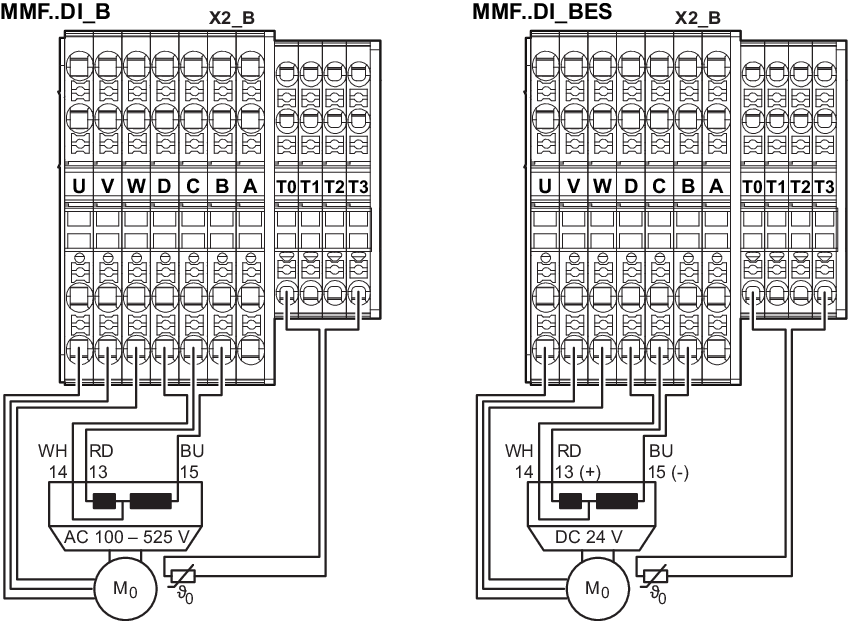
The connection diagrams of 2 or 3 motors can be found in the product manual > chapter Connection diagrams for MMF32 group drive.
