Reference travel

For the referencing of axes, a controller-based reference travel is available for all axis types (MOVI-C® axis, virtual axis, CiA402 axis). Reference travel is realized via the MOVI-C® CONTROLLER. The inverter-based reference travel is available additionally for MOVI-C® axes. This uses the inverter function FCB 12 to reference the axis.

You can select from several reference travel types. All reference travel settings can also be specified from the application at any time using the MC_SEW_ConfigHoming function block. The settings in the logical device are transferred to the inverter when the MOVI-C® CONTROLLER is started.

For reference travel types with reference cams or limit switches, the sensors must be wired to the following inputs of the inverter:

  • Reference cam – DI 03
  • Negative limit switch – DI 04
  • Positive limit switch – DI 05

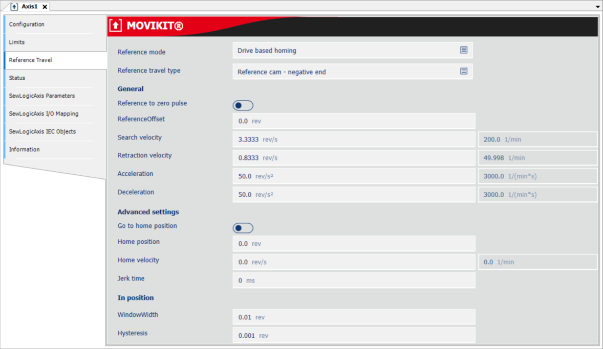
Depending on the axis type, the parameters described below are written to the inverter in non-volatile memory when the MOVI-C® CONTROLLER starts up:

Parameter designation

Description

Reference mode

Setting of the referencing mode type:

  • Controller based homing – Reference travel is realized in the MOVI-C® CONTROLLER.
  • Drive based homing – When reference travel is performed via MC_Home, the inverter function "Reference travel" is run. Currently this operating mode is only supported by MOVI-C® axes.

Reference travel type

Setting of the reference travel type:

  • Deactivated – Reference travel is deactivated. Referencing is not possible.
  • Zero pulse – negative direction – Referencing is performed to the zero pulse (reference pulse of the encoder). The first search direction is negative. The reference point is the first zero pulse. A reference cam is not required.
  • Reference cam – negative end – Referencing is performed to the negative end of the reference cam. The first search direction is negative.
  • Reference cam – positive end – Referencing is performed to the positive end of the reference cam. The first search direction is positive.
  • Limit switch positive/negative – The reference point is at the end of the left/right limit switch.
  • Referencing without travel – The reference point is set at the current position of the drive. The drive does not perform any movement.
  • Reference cam flush – positive end – Referencing is performed to a reference cam. The reference cam must start just before or in line with the positive hardware limit switch and must project into the limit switch. Reference travel starts at search speed in positive direction. When the negative end of the reference cam is reached, the drive turns and leaves the reference cam again at retraction speed. If no reference cam is found in the positive direction of rotation, an error is triggered at the positive limit switch. If the positive limit switch is hit during deceleration on the reference cam, this is ignored and referencing is continued.
  • Reference cam flush – negative end – Referencing is performed to a reference cam. The reference cam must start just before or in line with the negative hardware limit switch and must project into the limit switch. Reference travel starts at search speed in negative direction. When the positive end of the reference cam is reached, the drive turns and leaves the reference cam again at retraction speed. If no reference cam is found in the negative direction of rotation, an error is triggered at the negative limit switch. If the negative limit switch is hit during deceleration on the reference cam, this is ignored and referencing is continued.


  • Fixed stop positive/negative – Referencing is performed to a fixed stop. The system must be designed so that the fixed stop can withstand the load from the respective speed without damage. The search direction is positive/negative. The reference point is the positive/negative fixed stop. Because any hardware limit switches connected to the inverter are ignored in this reference travel configuration, there is a risk of jamming and crushing.
  • Absolute position of encoder – Only the reference bit is set and the current position of the encoder is adopted as the actual position. The reference travel type is only useful for encoders that have a direct reference to the system, e.g. linear encoders. The reference offset parameter is not used.
  • Use drive settings – Setting for when a reference type of a particular device is not listed in this list. Only used for drive-based reference travel. With this setting, the software module does not parameterize the reference travel of the drives. The reference travel of the drives can be configured manually using the device-specific engineering tool.

General

Reference to zero pulse

Setting for whether the zero pulse (reference pulse of the encoder) is used as the reference point. The parameter is used for the following reference travel types:

  • Reference cam – negative end
  • Reference cam – positive end
  • Positive limit switch
  • Negative limit switch
  • Reference cam flush – positive limit switch
  • Reference cam flush – negative limit switch

Reference offset

Reference offset in user units

Search velocity

Speed in user units used to search for a reference cam or hardware limit switch.

Retraction velocity

Speed in user units used during reference travel in the following cases:

  • When leaving a reference cam or hardware limit switch. With the reduced speed, the drive can travel exactly to the end of the reference cam or limit switch.
  • When searching a zero pulse (reference pulse of the encoder).
  • During reference travel to a fixed stop

Acceleration

Acceleration at start or direction of rotation reversal of reference travel

Deceleration

Deceleration for stopping or direction of rotation reversal during reference travel

Advanced settings

Go to home position

Setting for whether a home position should be approached after reference travel.

  • Yes – The drive stops at the reference point.
  • No – The drive moves from the reference point to the home position with home velocity.

Home position

Home position

Home velocity

Homing speed

Jerk time

Jerk time

In position

Window width

Position window for homing

Hysteresis

Position hysteresis for homing

Velocity changeover before fixed stop

Trigger for switching from search speed to retraction speed:

  • Not selected
  • Limit switch
  • Reference cam

Dwell time at fixed stop

Duration in ms of how long the drive remains at the fixed stop once the value defined in the "Torque limit at fixed stop" parameter is reached. The drive is only referenced after this time.

Torque limit at fixed stop

Torque limit in % of nominal motor torque for referencing to fixed stop. Once this limit is reached, the drive remains at the fixed stop for as long as defined in the "Dwell time at fixed stop" parameter.