Performing readjustment
If, for the application, each member is to hit its limit switch to ensure mechanical alignment, readjustment can be used for this purpose. If, in addition, there is a mechanical offset between the limit switches of the two members, this can be defined using the "Reference offset per member".
The following diagram shows the sequence of referencing if readjustment is used for the "Positive limit switch" reference travel type:
- t < -1: Both members travel in the positive direction searching for the limit switches.
- t = -1: Member 1 reaches its limit switch first.
- t = 0: Both members decelerate to a speed of 0.
- t = 1: Both members move away again at negative speed.
- t = 2: The positive limit switch of member 1 is no longer actuated. Therefore, both members decelerate to a speed of 0.
- t = 3: Member 2 starts moving again since its limit switch has not yet been actuated.
- t = 5: The positive limit switch of member 2 is actuated.
- t = 6: Member 2 decelerates to a speed of 0.
- t = 7: Member 2 moves away from its limit switch again in the negative direction of travel.
- t = 8: The positive limit switch of member 2 is no longer actuated. Therefore, it decelerates to a speed of 0.
- t = 9: Both members have recorded their reference point, and referencing is complete.
|
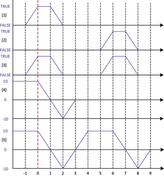
[1] | Positive limit switch for member 1 |
[2] | Positive limit switch for member 2 |
[3] | Logical OR-operation of the positive limit switch |
[4] | Speed of member 1 |
[5] | Speed of member 2 |
