Controller optimization with combined encoder evaluation in the inverter
If position control is performed in the inverter (e.g. via FCB 10), the additional function "Combined encoder evaluation" must be activated in the drive train.
To use the additional function "Combined encoder evaluation", proceed as follows. Note that the described procedure only covers the relevant details for configuring the additional function "Combined encoder evaluation" and controller optimization, and may vary under different conditions.
Prerequisite: The drive train of the lower-level axis and a software node with the MOVIKIT® StackerCrane are configured in MOVISUITE®.
- Configure the drive train
- In MOVISUITE®, configure the drive train and activate position control in the motor encoder.

- Determine load inertia
- Reduce the stiffness to 0.6 – 0.8, for example, and configure "Zero clearance" to 0% in the drive train configuration via the "Drive trains" > "Optimization DT1" configuration menu in the "Dynamic behavior" section.
- If possible, enter a calculated (see Workbench project planning) or estimated value in the configuration of the drive train in the "Drive trains" > "Optimization DT1" configuration menu in the "Mass moment of inertia" section as "J load (without gear unit)". This value refers to the motor shaft.
- Open manual mode via the [Open manual mode] button in the "Auxiliary tools" section.
- After referencing the drives, select the required travel option (e.g. "Speed-setpoint").
- Then determine the exact load inertia without payload by moving the axis back and forth, and apply this value.

- Optimize the speed controller
- Optimize the speed controller via the travel range without payload by configuring "Zero clearance" accordingly in the configuration of the drive train (20% ≈ carrying wheel/friction wheel, 70% ≈ gear wheel/chain) and increasing the stiffness step by step up to slight oscillation via the "Drive trains" > "Optimization DT1" configuration menu in the "Dynamic behavior" section.
- Then reduce the stiffness slightly so that no oscillation occurs or so that a visible noise of the torque signal is less than 10%, for example.
- Use suggested values for time constant and position controller
- Activate "Position control" and "Combined encoder evaluation" for the external encoder, and use the specified suggested value for the time constant in the configuration of the drive train via the "Drive trains" > "Drive train DT1" configuration menu. If required, perform a referencing procedure afterward.

- Use the suggested value in the drive train configuration in the "Drive trains" > "Optimization DT1" configuration menu in the "Position controller" section as the P gain of the position controller.
- Then check the positioning accuracy, speed, and torque using a positioning process ([Open Scope] button).
- If the suggested values do not lead to a satisfactory result, the following steps and/or the step "Extended optimization measures" must be performed.
- Determine the time constant of the mechanical system (natural frequency)
- Deactivate position control and thus the external encoder in the configuration of the drive train in the "Drive trains" > "Optimization DT1" configuration menu in the "Use" section so that the motor encoder is used.
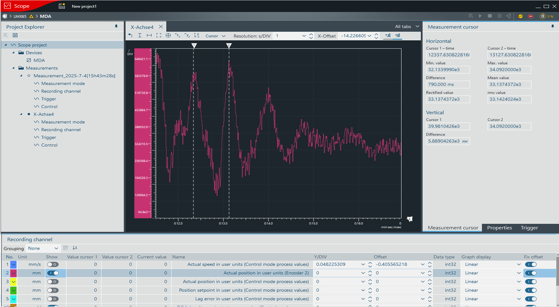
- Perform a scope recording of a stopping procedure with dynamic stop ramp without jerk or with brake application and ideally with payload and, if available, with maximum rope/belt length ([Open Scope] button).
- Measure the period duration of an oscillation after stopping via the actual position of the distance encoder (Actual position in user units, encoder 2) or alternatively based on the actual speed or the torque. Alternatively, you can measure the duration of a visible oscillation, e.g. on the mast of a storage/retrieval system.
- Enter the determined period duration as a time constant in the configuration of the drive train in the "Drive trains" > "Optimization DT1" configuration menu in the "Combined encoder evaluation" section.
- Optimize the P gain of the position controller
- Deactivate position control for the motor encoder in the drive train.
- Activate position control for the external encoder in the drive train.
- When positioning via the motor encoder and the "Stiffness" and "Zero clearance" parameters, the suggested value for the P gain of the position controller is always half the P gain of the speed controller. When positioning via a distance encoder, the suggested value for the P gain is lower.
- In the configuration of the drive train in the "Drive trains" > "Optimization DT1" configuration menu, activate the "Advanced settings" menu, reduce the suggested value for the P gain of the position controller and switch to position-controlled manual mode or to load cycling so that the external encoder is active.
- Slowly increase the P gain of the position controller up to the desired positioning accuracy (max. 50% of the P gain speed controller) with the lowest possible oscillation amplitude.
- Check optimized configuration values
- Move with and without payload at low and high accelerations
- Move at slow and fast speeds with and without payload
- Perform extended optimization measures
- Perform the following steps if the previous steps do not yet deliver a satisfactory result:
- Positioning accuracy not reached
- If the positioning process is not accurate enough when the suggested value for the P gain of the position controller is reached, but the system does not oscillate, increase the stiffness of the speed controller in the configuration of the drive train in the "Drive trains" > "Optimization DT1" configuration menu. First, reduce the P gain of the position controller again, and then gradually approach the new maximum value of the P gain.
- Oscillation before reaching the desired positioning accuracy
- If the system starts oscillating and the positioning process is not accurate enough, gradually increase the time constant of the combined encoder evaluation by 10% in the configuration of the drive train in the "Drive trains" > "Optimization DT1" configuration menu. If this does not lead to a better result, weaken the speed controller by reducing the stiffness, and re‑optimize the position controller by adjusting the P gain.
