Controller optimization with combined encoder evaluation in the software module
If position control is performed in the MOVI-C® CONTROLLER with MOVIKIT® (StackerCrane) MultiAxisController, the additional function "Combined encoder evaluation" must be activated in the MOVIKIT® (StackerCrane) MultiAxisController. The corresponding function in the inverter cannot be used in this case.
To use the additional function "Combined encoder evaluation", proceed as follows. Note that the described procedure only covers the relevant details for configuring the additional function "Combined encoder evaluation" and controller optimization, and may vary under different conditions.
Prerequisite: The drive train of the lower-level axis and a software node with the MOVIKIT® (StackerCrane) MultiAxisController are configured in MOVISUITE®.
- Configure the drive train
- Configure the drive train and the external encoder in MOVISUITE®. Do not activate combined encoder evaluation on the external encoder.

- The MOVIKIT® (StackerCrane) MultiAxisController automatically configures position control in the drive train in the motor encoder in such a way that the motor encoder position is passed on to the MOVI-C® CONTROLLER. The calculations for the combined encoder evaluation with the external encoder are made in the MOVI-C® CONTROLLER, since this is where position control is performed.
- Configure the software module
- To activate the additional function "Combined encoder evaluation" in the configuration of the MOVIKIT® (StackerCrane) MultiAxisController, select the option "Motor encoder and external encoder" as the "Encoder source" under "Module configuration" > "Encoder evaluation" in the "Position controller" section. The suggested value of 0.1 s can initially be used as the time constant.
- Generate the IEC project and open the optimization monitor
- Generate the IEC project via MOVISUITE® and add the trace template in the IEC Editor via the menu "Tools" > "Scripting" > "Scripts" > "T" > "Trace_MultiAxisController". In the [Online] menu, click the [Login] menu entry, open the optimization monitor via the Devices tree, and switch to control mode by clicking the two [Control] buttons (operating mode of motion control and optimization functions).
- Deactivate external encoder
- Deactivate the external encoder using the [Deactivate all external encoder] button in the "EncoderEvaluation" menu.

- Determine load inertia
- Reduce the stiffness to 0.6 – 0.8, for example, and configure "Zero clearance" to 0% via the "Inverter settings" menu in the "Dynamic behavior - speed controller" section.
- After referencing the drives, select the required travel option (e.g. "Speed-controlled").
- If possible, enter a calculated or estimated value for the J load for each axis in the "Inverter settings" menu. This value refers to the motor shaft.
- Then determine the exact load inertia without payload by moving the axis back and forth, and apply this value via the [Transmit measured mean value to inverter and optimize speed controller] button.

- Optimize the speed controller
- Optimize the speed controller via the travel range without payload by configuring "Zero clearance" accordingly (20% ≈ carrying wheel/friction wheel, 70% ≈ gear wheel/chain) and increasing the stiffness step by step up to slight oscillation in the "Inverter settings" menu in the "Dynamic behavior - speed controller" section.
- Then reduce the stiffness slightly so that no oscillation occurs or so that a visible noise of the torque signal is less than 10%, for example.

- Use suggested values for time constant and position controller
- Activate the external encoder via the [Deactivate all external encoder] button in the "EncoderEvaluation" menu so that the suggested value from MOVISUITE® is used as the time constant. Combined encoder evaluation is now active. If required, perform a referencing procedure afterward.
- Use the suggested 2% (MOVIKIT® StackerCrane MultiAxisController) or 100% (MOVIKIT® MultiAxisController) of the suggested value in the "Control loop functions" menu under "Position controller" for the P gain of the position controller, or gradually approach an appropriate value.

- Then check the positioning accuracy, speed, and torque using a trace recording of a positioning process.
- If the suggested values do not lead to a satisfactory result, the following steps and/or the step "Extended optimization measures" must be performed.
- Determine the time constant of the mechanical system (natural frequency)
- To use the motor encoder, deactivate the external encoder using the [Deactivate all external encoder] button in the "EncoderEvaluation" menu.
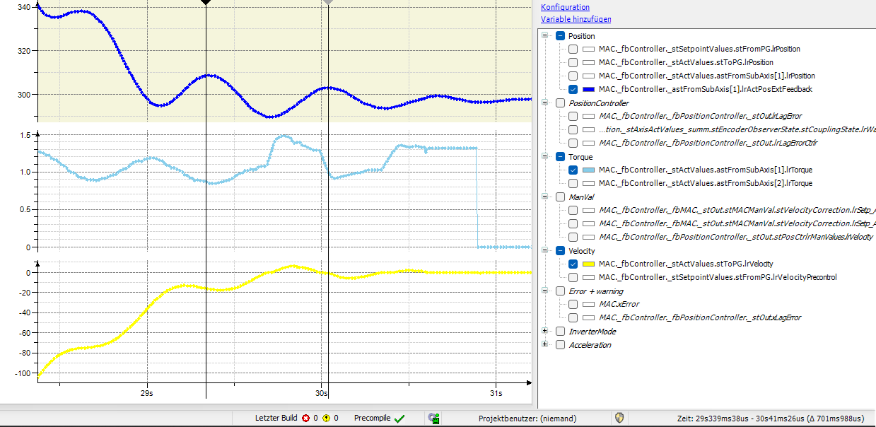
- Perform a trace recording of a stopping procedure with dynamic stop ramp without jerk or with brake application and ideally with payload and, if available, with maximum rope/belt length.
- Measure the period duration of an oscillation after stopping via the actual position of the distance encoder (lrActPosExtFeedback) or based on the actual speed and torque. Alternatively, you can measure the duration of a visible oscillation, e.g. on the mast of a storage/retrieval system.
- Enter the determined period duration as a time constant for combined encoder evaluation in the "EncoderEvaluation" menu.

- Optimize the P gain of the position controller
- Activate the external encoder via the [Deactivate all external encoder] button in the "EncoderEvaluation" menu so that combined encoder evaluation is active.
- Reduce the suggested value for the P gain of the position controller to a minimum (e.g. 2%) in the "Control loop functions" menu in the "Position controller" section, and incrementally increase the value until the desired result is achieved.

- Check the positioning accuracy, speed, and torque using a trace recording. The oscillation should now be reduced to a minimum.
- Check optimized configuration values
- Move with and without payload at low and high accelerations
- Move at slow and fast speeds with and without payload
- Perform extended optimization measures
- Perform the following steps if the previous steps do not yet deliver a satisfactory result:
- Positioning accuracy not reached
- If the positioning process is still not accurate enough with the setting "100%" for the P gain of the position controller, but the system does not oscillate, increase the stiffness of the speed controller in the "Inverter settings" menu in the "Dynamic behavior - speed controller" section. First, reduce the P gain of the position controller in the "Control loop functions" menu in the "Position controller" section, and then gradually approach the new maximum value for the P gain.
- Oscillation before reaching the desired positioning accuracy
- If the system starts oscillating and the positioning process is not accurate enough, gradually increase the time constant of the combined encoder evaluation by 10% in the "EncoderEvaluation" menu. If this does not lead to a better result, weaken the speed controller by reducing the stiffness in the "Inverter settings" menu in the "Dynamic behavior - speed controller" section, and optimize the position controller again by adjusting the P gain in the "Control loop functions" menu in the "Position controller" section.
