Arrangement of the modules
The modules can be arranged in one or two rows.
Single-row setup – MDR91B.. supply and regenerative module
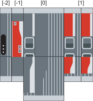
Position | Description |
|---|---|
-2 | MDS90A.. switched-mode power supply module |
-1 | Master module UHX45A/MDM90A |
0 | MDR91B.. supply and regenerative module |
1 | Axis modules MDA90A.. and MDD9.A.. |
Observe the following information:
- Always arrange the MDA90A.. and MDD9.A.. axis modules directly to the right of the MDR91B.. supply and regenerative module, based on the nominal DC link current (descending) from left to right, starting with the axis module with the highest nominal DC link current.
- As an alternative to the specification in the table, you can arrange the UHX45A/MDM90A master module to the far right.
Single-row setup – MDR90B.. supply and regenerative module
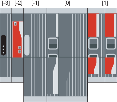
Position | Description |
|---|---|
-3 | MDS90A.. switched-mode power supply module |
-2 | Master module UHX45A/MDM90A |
-1 | MDF90B.. filter module |
0 | MDR90B.. supply and regenerative module |
1 | Axis modules MDA90A.. and MDD9.A.. |
Observe the following information:
- Always arrange the MDF90B.. filter module directly to the left of the MDR90B.. supply and regenerative module.
- Always arrange the MDA90A.. and MDD9.A.. axis modules directly to the right of the MDR90B.. supply and regenerative module, based on the nominal DC link current (descending) from left to right, starting with the axis module with the highest nominal DC link current.
- As an alternative to the specification in the table, you can arrange the UHX45A/MDM90A master module to the far right.
Two-row setup – MDR91B.. supply and regenerative module
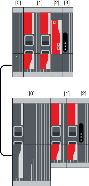
Position | Description |
|---|---|
0 | MDC90A-0001/0002.. capacitor modules |
1 | Axis modules MDA90A.. and MDD9.A.. |
2 | Master module UHX45A/MDM90A |
3 | MDS90A.. switched-mode power supply module |
Position | Description |
|---|---|
0 | MDR91B.. supply and regenerative module |
1 | Axis modules MDA90A.. and MDD9.A.. |
2 | MDS90A.. switched-mode power supply module |
Observe the following information:
- Always arrange the MDR91B.. supply and regenerative module in the main row.
- Always arrange the MDC90A-0001/0002.. capacitor modules to the far left In the auxiliary row.
- Always arrange the MDA90A.. and MDD9.A.. axis modules in the main row directly to the right of the MDR9.B.. supply and regenerative module, based on the nominal DC link current (descending) from left to right, starting with the axis module with the highest nominal DC link current.
- Arrange the UHX45A/MDM90A master module in the auxiliary row to the right of the axis modules. As an alternative to the specification in the table, you can also arrange the UHX45A/MDM90A master module to the right of the axis modules in the main row.
- Place an MDS90A.. switched-mode power supply module to the far right in the main or auxiliary row.
Two-row setup – MDR90B..supply and regenerative module
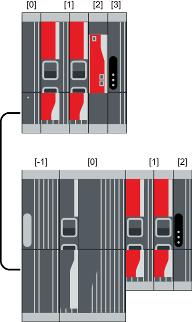
Position | Description |
|---|---|
0 | MDC90A-0001/0002.. capacitor modules |
1 | Axis modules MDA90A.. and MDD9.A.. |
2 | Master module UHX45A/MDM90A |
3 | MDS90A.. switched-mode power supply module |
Position | Description |
|---|---|
-1 | MDF90B.. filter module |
0 | MDR90B.. supply and regenerative module |
1 | Axis modules MDA90A.. and MDD9.A.. |
2 | MDS90A.. switched-mode power supply module |
Observe the following information:
- Always arrange the MDR90B.. supply and regenerative module in the main row.
- Always arrange the MDC90A-0001/0002.. capacitor modules to the far left In the auxiliary row.
- Always arrange the MDA90A.. and MDD9.A.. axis modules in the main row directly to the right of the MDR9.B.. supply and regenerative module, based on the nominal DC link current (descending) from left to right, starting with the axis module with the highest nominal DC link current.
- Always arrange the MDA90A.. and MDD9.A.. axis modules in the auxiliary row directly to the right of the MDC90A-0001/0002.. capacitor modules, based on the nominal DC link current (descending) from left to right, starting with the axis module with the highest nominal DC link current.
- Arrange the UHX45A/MDM90A master module in the auxiliary row to the right of the axis modules. As an alternative to the specification in the table, you can also arrange the UHX45A/MDM90A master module to the right of the axis modules in the main row.
- Place an MDS90A.. switched-mode power supply module to the far right in the main or auxiliary row.
