Mounting the V-belt drive
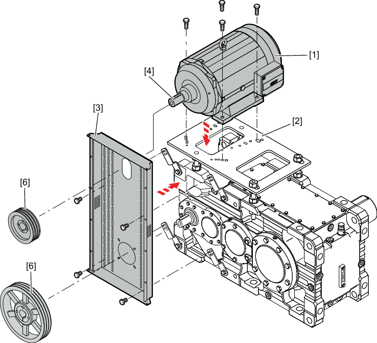
- Mount the motor [1] on the base plate [2] (the retaining screws are not included in the delivery).
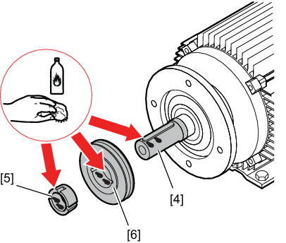
- Clean and degrease the shafts [4], the taper bushings [5], and the belt pulleys [6].
- Use the specified holding fixtures to secure the V-belt guard [3]. Take into account the room required for positioning and tightening the belts, as well as the desired direction in which the guard will be opened.
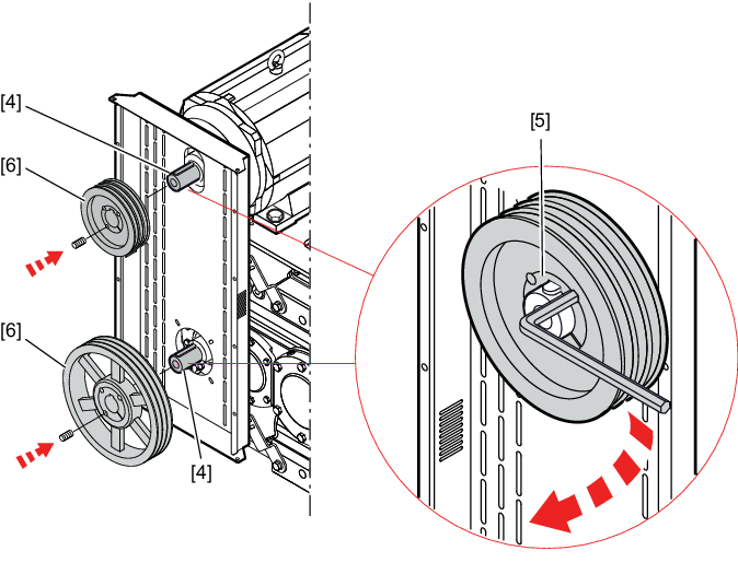
- Mount the belt pulleys [6] completed with taper bushings on the gear unit and motor shaft [4]. Apply a little grease to the screws of the taper bushings and fill the unoccupied boreholes with grease to prevent soiling. Evenly tighten the locking screws of the taper bushings [5]. While tightening the screws, apply some light strokes to the hub to make the connection fit properly.
The following table shows the tightening torques for the taper bushings [5].
Dimensions | Wrench size | Number of screws | Tightening torque in Nm |
|---|---|---|---|
TB 1008, 1108 | 3 | 2 | 5.7 |
TB 1210, 1215, 1310, 1610, 1615 | 5 | 2 | 20 |
TB 2012 | 6 | 2 | 31 |
TB 2517 | 6 | 2 | 49 |
TB 3020, 3030 | 8 | 2 | 92 |
TB 3525, 3535 | 10 | 3 | 115 |
TB 4040 | 12 | 3 | 172 |
TB 4545 | 14 | 3 | 195 |
TB 5050 | 14 | 3 | 275 |
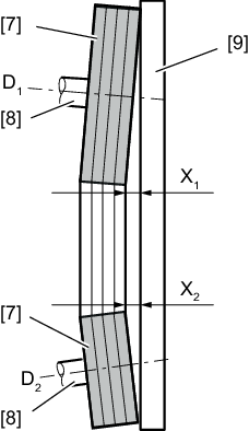
- Position the belt pulleys [7] as closely as possible to the shaft shoulder [8]. If the rim widths of the two disks deviate from each other, this must be taken into account during positioning. Check the alignment of the belt pulleys before and after you have tightened the taper bushings using a straightedge [9] or a suitable alignment tool. For the maximum permitted misalignment, refer to the following table.
Pulley diameter D1, D2 in mm | Maximum permitted distance X1, X2 |
|---|---|
112 | 0.5 |
224 | 1.0 |
450 | 2.0 |
630 | 3.0 |
For other diameter values, you have to interpolate the intermediate values for X1 and X2.
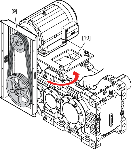
- Place the V-belts [9] onto the belt pulleys and tighten them by adjusting the base plate using the threaded rods [10].
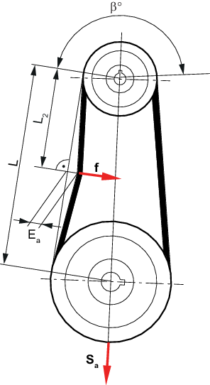
- Check the belt tension with a suitable preload measuring device. If no special measuring device is available, you can estimate the preload using the method described below.
- Refer to the following table to determine the test force [f] required to deflect the belt by a specific distance [Ea] in the middle of the free belt length if the belt has the correct tension.
- Compare the measured values with the values in the table (on the following pages). Adjust the tension of the belt until the measured values correspond to the values of the table.
- Tighten all the screws and nuts and once again check the alignment of the belt pulleys as well as the correct tension of the belt.
- Adhere to the correct belt tension.
- Install the protection cover for the V-belt drive properly.
- Check the initial belt tension after about 24 hours of operation to compensate for the initial stretching of the V-belts. At the same time, also review the tight fit of the taper bushings and their locking screws.
INFORMATION

The data in the following table only applies if V-belts from SEW‑EURODRIVE are used. When using V-belts from other manufacturers, the user is responsible for determining the belt tension and for observing the permitted bending moments.
Additional information
