ROTEX® coupling
Mounting the coupling
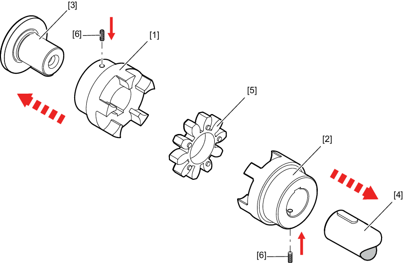
- Mount the hubs [1][2] onto the input and output shafts [3][4].
- Insert the spider [5] or DZ elements into the cam section of the input and output hubs [1][2].
- Move the gear unit/motor in axial direction until dimension E is reached. If the gear unit and motor have already been installed permanently, set dimension E by moving the hubs [1][2] axially on the input and output shafts [3][4].
- Secure the hubs by tightening the set screws [6].
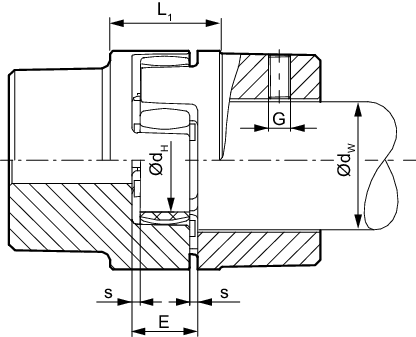
Coupling | Mounting dimensions | Retaining screw | |||
|---|---|---|---|---|---|
E | s | dH | G | Tightening torque | |
14 | 13 | 1.5 | 10 | M4 | 1.5 |
19 | 16 | 2 | 18 | M5 | 2 |
24 | 18 | 2 | 27 | M5 | 2 |
28 | 20 | 2.5 | 30 | M8 | 10 |
38 | 24 | 3 | 38 | M8 | 10 |
42 | 26 | 3 | 46 | M8 | 10 |
48 | 28 | 3.5 | 51 | M8 | 10 |
55 | 30 | 4 | 60 | M10 | 17 |
65 | 35 | 4.5 | 68 | M10 | 17 |
75 | 40 | 5 | 80 | M10 | 17 |
90 | 45 | 5.5 | 100 | M12 | 40 |
100 | 50 | 6 | 113 | M12 | 40 |
110 | 55 | 6.5 | 127 | M16 | 80 |
125 | 60 | 7 | 147 | M16 | 80 |
140 | 65 | 7.5 | 165 | M20 | 140 |
160 | 75 | 9 | 190 | M20 | 140 |
180 | 85 | 10.5 | 220 | M20 | 140 |
Additional information
