Size X170 – 320
INFORMATION

- Included in the scope of delivery:
- Retaining screws [3] and end plate [4]
- Not included in the scope of delivery:
- Threaded rod [2], nut [5], retaining screw [6], ejector screw [8]
- Apply some assembly paste, such as NOCO-Paste onto the hollow shaft [7] and onto the shaft end of the machine shaft [1].
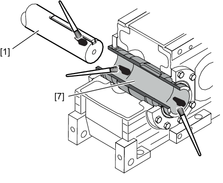
[1] | Machine shaft |
[7] | Hollow shaft |
- Use the retaining screws [3] to attach the end plate [4] centrically to the hollow shaft [7] and thread the threaded rod [2] into the machine shaft [1]. Observe the following thread sizes of the threaded rods [2].
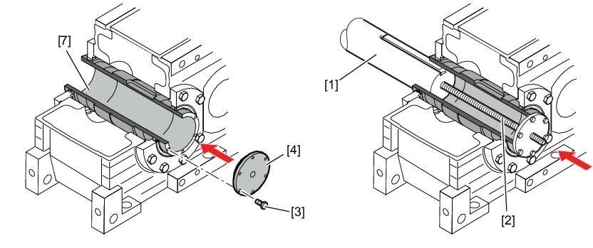
[1] | Machine shaft | [4] | End plate |
[2] | Threaded rod | [7] | Hollow shaft |
[3] | Retaining screw |
|
Size | Strength class 8.8 |
|---|---|
X..A170 – 230 | M30 |
X..A240 – 300 | M36 |
X..A310 – 320 | M42 |
Observe the following information on the retaining screws [3].
Size | Thread size for | Tightening torque |
|---|---|---|
Assembly/ | ||
X..A170 – 190 | M10 x 30 | 78 |
X..A200 – 230 | M12 x 30 | 135 |
X..A240 – 300 | M16 x 30 | 330 |
X..A310 – 320 | M20 x 50 | 645 |
INFORMATION
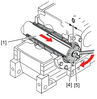
Mounting is easier if you first apply assembly paste to the threaded rod and the nut.
- Tighten the machine shaft [1] with the nut [5] until the shaft end of the machine shaft [1] and the end plate [4] meet.
- Loosen the nut [5]. Remove the threaded rod [2].
[1] | Machine shaft |
[4] | End plate |
[5] | Nut |
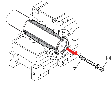
[2] | Threaded rod |
[5] | Nut |
- Secure the machine shaft [1] with the retaining screw [6]. The retaining screw is also to be locked with a suitable threadlocker. Observe the following information on the retaining screw [6].
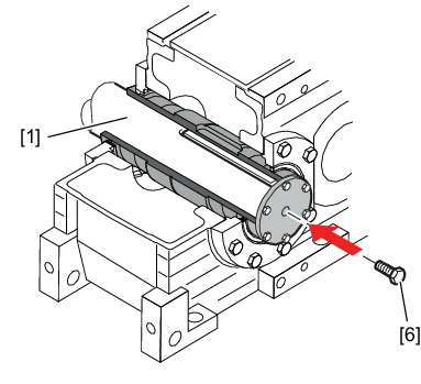
[1] | Machine shaft |
[6] | Retaining screw |
Size | Retaining screw | Tightening torque in Nm |
|---|---|---|
X..A170 – 230 | M30 | 1590 |
X..A240 – 300 | M36 | 2760 |
X..A310 – 320 | M42 | 4410 |
- Mount the protection cover dust-tight to the gear unit.
