Frictional encoder coupling
If the coupling of the external encoder to the motor encoder is frictional, i.e. subject to slip, or if the spring movement is very large compared to the motor travel to be monitored, additional slip monitoring is required.
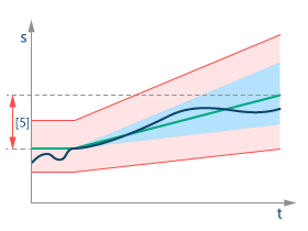
Slip monitoring always refers to the distance traveled by the motor encoder [green line], so that the slip error window [3] or the slip warning window [4] increases with the motor distance traveled [green line] according to the relative configuration of the slip error or slip warning window.

For example, if the slip warning window is set to 5%, 5% of the motor travel is always permitted as an error window. After 100 mm motor travel, the slip warning window has increased from 0 mm at the beginning to 5 mm.
As the windows [3] or [4] can become very large with large motor movements, the slip window calculation is cleared after the slip period [5] and starts again at 0. The slip-related error is also cleared at this point, i.e. the motor encoder is set to the position of the external encoder, provided this is permitted by the current slip window. Clearing after the slip period [5] is also essential for endless drives, as otherwise the error window would become infinitely large. It is recommended to set a value for the slip period that is approximately one tenth of a travel cycle. For example, if the smallest travel cycle is 1 m, then 10 cm is a good slip period value.
Since every frictional connection also has positive coupling errors (slack, encoder noise, spring movements), it is necessary to set an absolute warning and error window for frictional connections as well. This combination of coupling error types is illustrated in the following graphic by adding the absolute error/warning window [red] and the relative error/warning window [blue].