System overview
The following figure shows an extremely simplified system structure of a safe brake system with one brake [A] and two brakes [B] and an integrated brake test.
[A] | [B] |
|---|---|
|
|
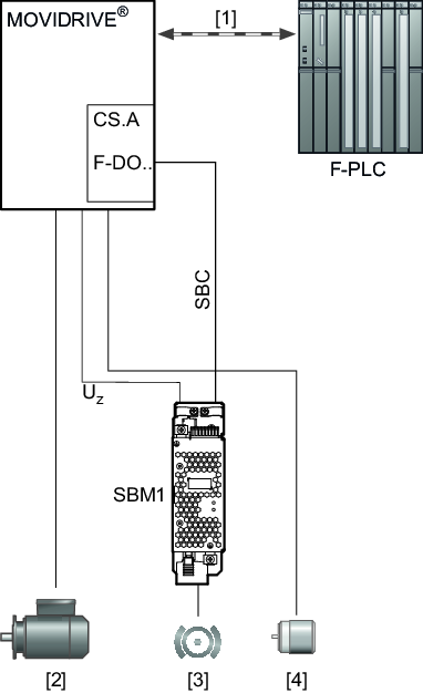
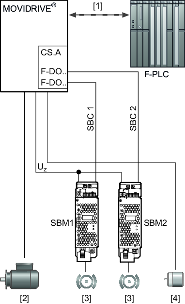
MOVIDRIVE® | MOVIDRIVE® modular/system/technology frequency inverter |
F-PLC | Higher-level safety controller |
CS.A | MOVISAFE® CS..A safety option |
[1] | Safe communication |
[2] | Motor |
[3] | Brake(s) |
[4] | Encoder mounted on the motor |
SBM1/2 | SBM safe brake module |
UZ | DC link voltage |
SBC, SBC 1, 2 | Control signal(s) for safe control of the brake(s) and for controlling the brake(s) during an active brake test |
F-DO.. | Safe digital output |
