Position of motor terminal box and cable entry
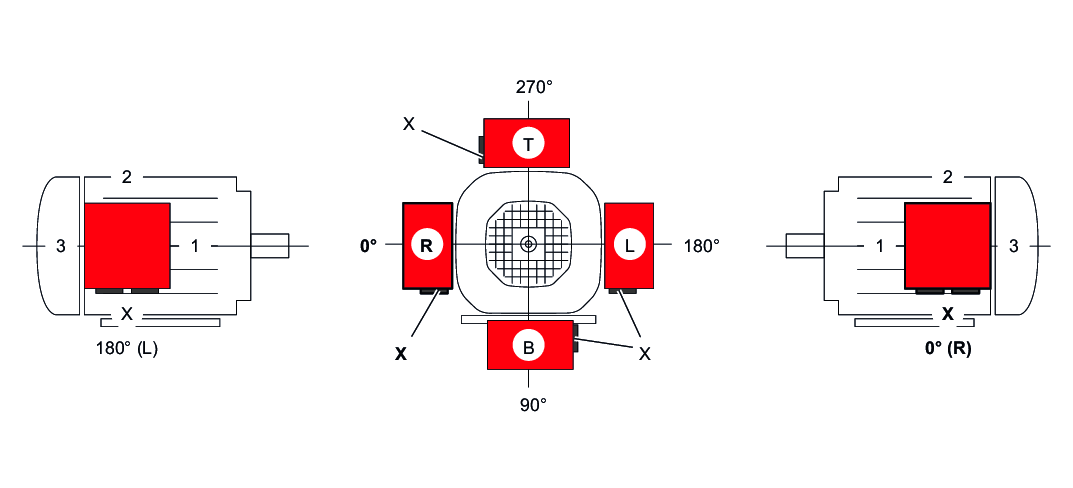
The position of the motor terminal box has so far been indicated with 0°, 90°, 180°, or 270° as viewed onto the fan guard (B-side), see the following figure. A change to DIN EN 60034-1 stipulates that the following designation has to be used for the terminal box position of foot-mounted motors in the future:
- View of the output shaft = A-side
- Designation as R (right), B (bottom), L (left), and T (top)
This new designation applies to foot-mounted motors without a gear unit in mounting position B3 (= M1). For gearmotors, the previous designation is retained and is still specified with 0°, 90°, 180°, and 270° when looking at the fan guard = B-side. The following figure shows both designations. If the mounting position of the motor changes, R, B, L, and T are rotated accordingly. For motor mounting position B8 (= M3), T is at the bottom.
The position of the cable bushing can also be selected. "X" (= normal position), "1", "2", or "3" are possible, as shown in the following figure.
Without special information on the terminal box, the 0° version is supplied with cable bushing "X". For mounting position M3, SEW-EURODRIVE recommends selecting cable bushing "2".
For DR2S56.., DR2S63.., and DRN63.. motors, the terminal box is cast on the stator, which is why only the cable entries "X" and "2" are possible. Exception: This restriction does not apply with IS plug connector.
With terminal box position 90° (B), check whether the gearmotor must be supported.
The position of the terminal box is not given on the nameplate.
