Setting: RS485, FIELDBUS, SBus
With this setting, the control word defined in the process output data channel is updated by the set control signal source (RS485 / FIELDBUS / system bus).
The digital inputs and the IPOSplus® control program continue to be involved in the control process.
NOTICE

For safety reasons, you must also always enable the frequency inverter at the terminals for control via process data. Consequently, you must wire or program the terminals in such a way that the inverter is enabled via the digital inputs.
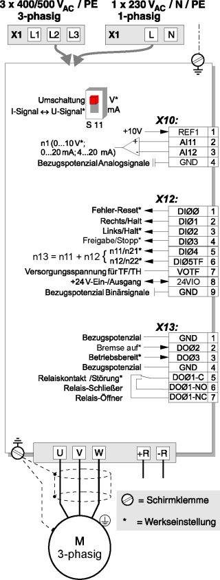
The following figure gives an example of terminal wiring and parameter setting for controlling the frequency inverter solely using process data.
| X12 |
DI00 = Fault reset | |
DI01 = CW/Stop | |
DI02 = CCW/Stop | |
DI03 = Enable/Stop | |
DI04 = n11/n21 | |
DI05TF = n12/n22 | |
VOTF = Supply voltage for TF/TH | |
24VIO4 = + 24 V input/output | |
DGND = Reference potential for binary signals | |
X13 | |
GND = Reference potential for binary signals | |
DO02 = Brake released | |
DO03 = Ready | |
GND = Reference potential | |
DO01-C = Relay contact/fault | |
DO01-NO = Normally open contact relay | |
DO01-NC = Normally closed contact relay | |
8674167947 | |
