Inertia properties
The following inertia properties must be defined for all arm sections of the selected kinematic model.
INFORMATION

For the TRIPOD_RRR_M10/TRIPOD_RRRR_M10/TRIPOD_RRRRR_M10, all three upper arms and all six forearms must each have identical masses, centers of gravity and inertias. The "Copy arm properties" button facilitates correct parameterization.
Parameter designation | Description |
|---|---|
Mass | Mass of the respective arm section. |
Center of gravity (X, Y, Z) | Center of gravity of the respective arm section. X, Y, and Z refer to the LCS (Link Coordinate System) of the arm section. |
Inertia (XX, YY, ZZ, XY, XZ, ZX) | Inertia matrix around the center of gravity. X, Y, and Z refer to the LCS (Link Coordinate System) of the respective arm section. |
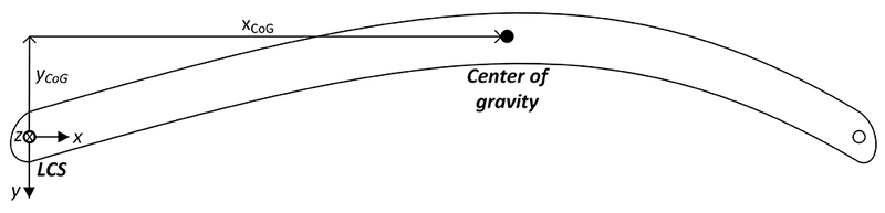
The origin of the LCS (Link Coordinate System) of each arm section is at the beginning of the arm section in the joint (see figure). The z-axis points in positive axis direction (along the output shaft of the drive). The x-axis normally points to the next joint, i.e. to the subsequent LCS.
The LCS of all kinematic models are shown in chapter Functional description for the respective kinematic model and can be displayed in the 3D simulation. As a general rule, and in particular if the Cartesian assignment is unequal to 0, it is recommended to use the LCS in the 3D simulation of the RobotMonitor as a guide (3D Simulation > Control Panel > Coordinate Systems > Links).
For ROLLER_GANTRY_RR_M10 kinematic models, the following parameters are additionally displayed in the "Inertia properties" configuration menu:
Parameter designation | Description |
|---|---|
Belt pulleys: Inertia | Mass moment of inertia of all belt pulleys together |
Belt: Inertia | Mass moment of inertia of the belt Can be calculated from |
1st Cartesian link: Mass | Mass of the first Cartesian joint that can only be moved in one direction:
|
2nd Cartesian link: Mass | Mass of the second Cartesian joint that can be moved in two directions:
|
