MOVIGEAR® performance DSI terminal assignment
Attach units without a plug connector to the terminals as follows:
- De-energize the device. Pay attention to the 5 safety rules in chapter "Carrying out electrical work safely". Afterwards, wait 5 minutes.
- Let the device cool sufficiently before touching it.
- Secure the output shaft against rotation. In this way, you will avoid electric shocks caused by regenerative operation when the shaft is turned.
- Undo the screws of the electronics cover. Remove the electronics cover.
- Route the cables through the cable glands into the connection box.
- If terminal X3 for connecting the braking resistor is occupied with an optional internal braking resistor and the capacity of this braking resistor is insufficient, you can alternatively connect an external braking resistor as follows:
- Undo the connections of the internal braking resistor.
- Insulate and fix the connections of the internal braking resistor. Ensure that the connections are electrically isolated from all other components.
- Connect the external braking resistor. When doing this, pay attention to the installation instructions of the unit and the external braking resistor.
- Connect the unit in accordance with the following terminal assignment.
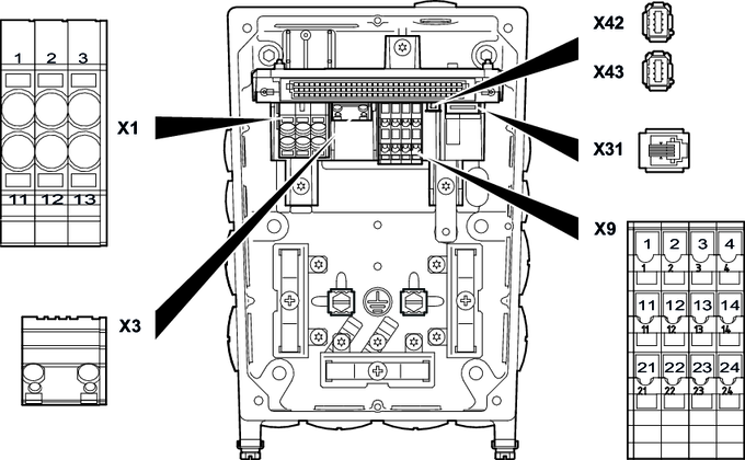
The following figure shows the terminals of MOVIGEAR® performance DSI:

The following table shows the terminal assignment of MOVIGEAR® performance DSI:
Terminal | No. | Marking | Function | |
|---|---|---|---|---|
X1 | 1 | Brown | L1 | Line connection, phase L1 – IN |
2 | Black | L2 | Line connection, phase L2 – IN | |
3 | Gray | L3 | Line connection, phase L3 – IN | |
11 | Brown | L1 | Line connection, phase L1 – OUT | |
12 | Black | L2 | Line connection, phase L2 – OUT | |
13 | Gray | L3 | Line connection, phase L3 – OUT | |
| – | – | PE | Protective earth connection |
X3 | 1 | – | BW | Braking resistor connection |
2 | – | BW | Braking resistor connection | |
X9 | 1 | Yellow | F_STO_P1 | Input STO+ |
2 | Yellow | F_STO_P1 | Input STO+ | |
3 | – | 0V24_OUT | 0 V 24 reference potential | |
4 | – | 24V_OUT | DC 24 V auxiliary output | |
11 | Yellow | F_STO_M | Input STO_ground | |
12 | Yellow | F_STO_M | Input STO_ground | |
13 | – | 24V_IN | DC 24 V supply | |
14 | – | 24V_IN | DC 24 V supply | |
21 | Yellow | F_STO_P2 | Input STO+ | |
22 | Yellow | F_STO_P2 | Input STO+ (to loop through) | |
23 | – | 0V24_IN | 0 V 24 reference potential | |
24 | – | 0V24_IN | 0 V 24 reference potential | |
X42 | 1 | – | TX+ | Transmit line + |
2 | – | TX- | Transmit line - | |
3 | – | RX+ | Receive line + | |
6 | – | RX- | Receive line - | |
X43 | 1 | – | TX+ | Transmit line + |
2 | – | TX- | Transmit line - | |
3 | – | RX+ | Receive line + | |
6 | – | RX- | Receive line - | |
X31 | 1 | – | 0V24_OUT | 0 V 24 reference potential |
2 | – | CAN_L | CAN Low connection | |
3 | – | CAN_H | CAN High connection | |
4 | – | 24V_OUT | DC 24 V auxiliary output | |
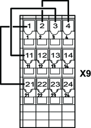
The following figure shows the factory-installed jumpers at the X9 terminals:

These jumpers are not present in the following designs:
- Designs with plug connectors with STO function
- Designs with CSB51A safety option
Additional information is available in the product manual > chapter Project planning for functional safety and chapter Connection variants functional safety.

