Shaft-mounted gear unit with TorqLOC® (customer shaft without contact shoulder)
Mount the drive unit on the shaft as follows:
- Perform the steps according to the chapter Installation notes.
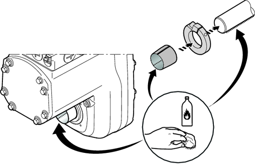
- Clean the customer shaft and the inside of the hollow shaft. Make sure that all grease and oil residues are removed.
- Mount the stop ring and the bushing on the customer shaft.
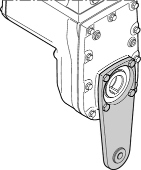
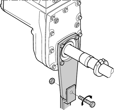
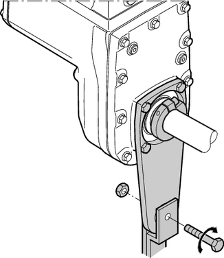
- Attach the torque arm to the drive unit. Observe chapter Torque arm. Installation of the drive unit without a torque arm is not permitted.
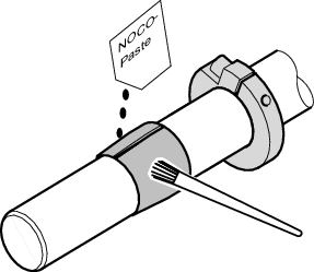
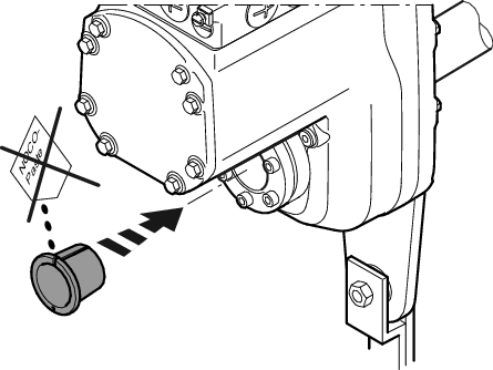
- Apply NOCO-Paste onto the bushing and spread it carefully.
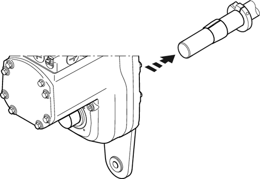
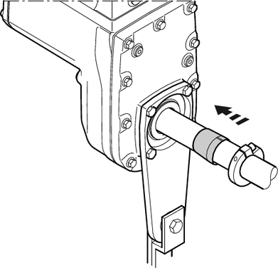
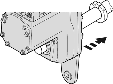
- Slide the gear unit onto the customer shaft.
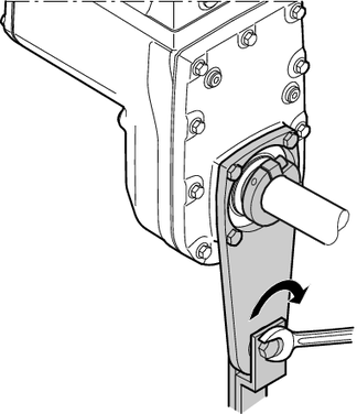
- Mount the torque arm onto the system structure/holding fixture (do not tighten the screws).
- Slide the bushing into the gear unit as far as its stop.
- Slide the stop ring onto the bushing. Mark the position of the stop ring.
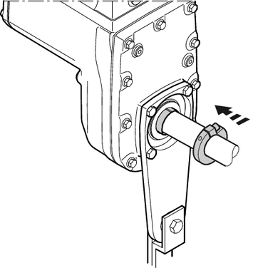
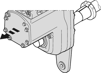
- Remove the torque arm from the holding fixture/system structure.
- Remove the gear unit from the customer shaft until the stop ring is accessible for installation.
- Make sure that the position of the stop ring has not changed (note the marking).
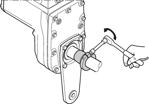
- Tighten the stop ring with the following torque:
- Standard design: 18 Nm
- Stainless steel: 7.5 Nm
- Slide the bushing and the gear unit onto the customer shaft up to the fixed stop ring.
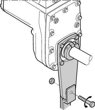
- Mount the torque arm onto the system structure/holding fixture again (do not tighten the screws).
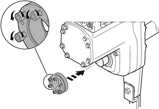
- Make sure that all screws are loosened and slide the shrink disk onto the hollow shaft.
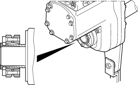
- Slide the counter bushing onto the customer shaft and into the hollow shaft.
- In the case of a gear unit with shaft shoulder, mount the shrink disk at the shaft shoulder up to the stop. In the case of a gear unit without shaft shoulder, mount the shrink disk at a distance of 6.5 mm to 7.5 mm from the gear unit housing.
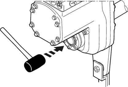
- Lightly hammer on the flange of the counter bushing to ensure that the bushing is firmly seated in the hollow shaft.
- Make sure that the customer shaft is seated in the counter bushing.
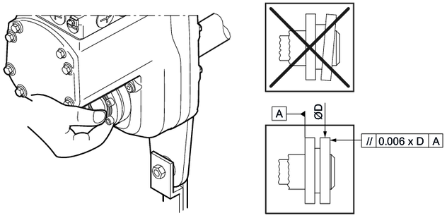
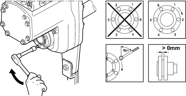
- Tighten the screws of the shrink disk only hand-tight and make sure that the outer rings of the shrink disk are plane-parallel.
- Tighten the locking screws by working round several times from one screw to the next (not in diametrically opposite sequence):
- The exact values for the tightening torques are located on the shrink disk.
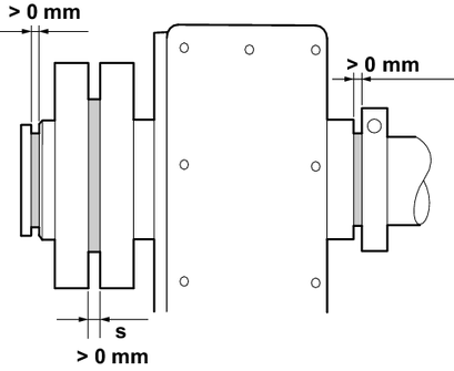
- After installation, make sure the remaining gap s between the outer rings of the shrink disks is > 0 mm.
- The remaining gap between the counter bushing and hollow shaft end, as well as the bushing and stop ring must be > 0 mm.
- Tighten the torque arm sufficiently. Observe chapter Torque arm.
