Derating due to the rotary field frequency
The specified nominal output current IN of the inverter is the effective value. The increased load on the power semiconductors has to be considered especially for slow rotating fields and rotating fields at standstill. In case of a rotating field at standstill, direct current that can correspond to the peak value of the sine current depending on the phase position is flowing.
It is particularly important to consider output frequencies fA < 3 Hz.
The following characteristic curves show the required derating depending on the output frequency fA of the various electronics covers:
Electronics cover size 1,
IN ≤ 4.0 A
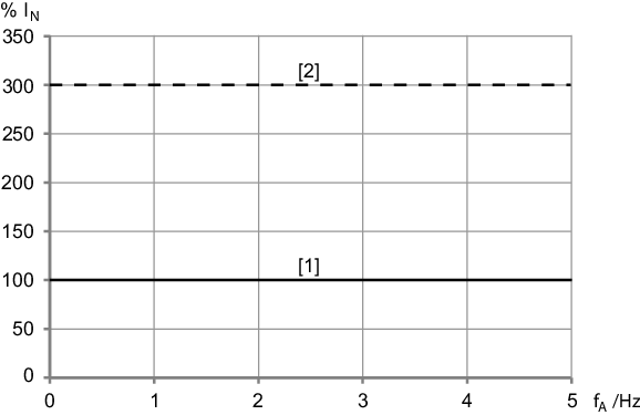
[1] | Continuous output current Icont at the smallest possible PWM frequency |
[2] | Temporally limited overload currentConfigure the overload current in the SEW Workbench. |
Electronics cover size 1,
IN = 5.5 A
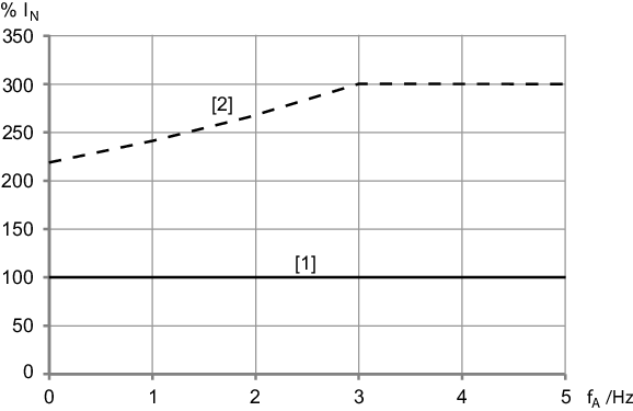
[1] | Continuous output current Icont at the smallest possible PWM frequency |
[2] | Temporally limited overload currentConfigure the overload current in the SEW Workbench. |
Electronics cover size 2,
IN ≤ 9.5 A
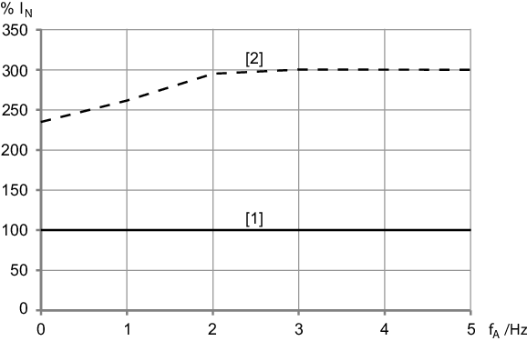
[1] | Continuous output current Icont at the smallest possible PWM frequency |
[2] | Temporally limited overload currentConfigure the overload current in the SEW Workbench. |
Electronics cover size 2,
IN = 12.5 A
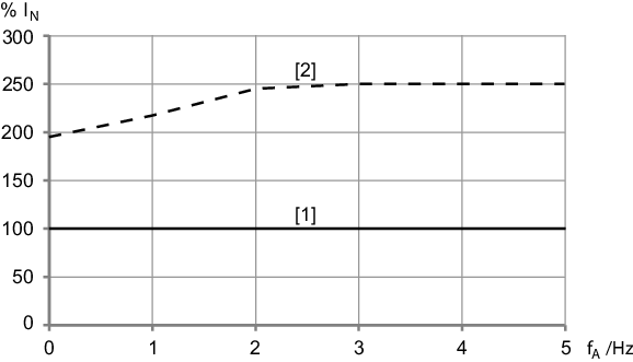
[1] | Continuous output current Icont at the smallest possible PWM frequency |
[2] | Temporally limited overload currentConfigure the overload current in the SEW Workbench. |
Electronics cover size 2,
IN = 16.0 A
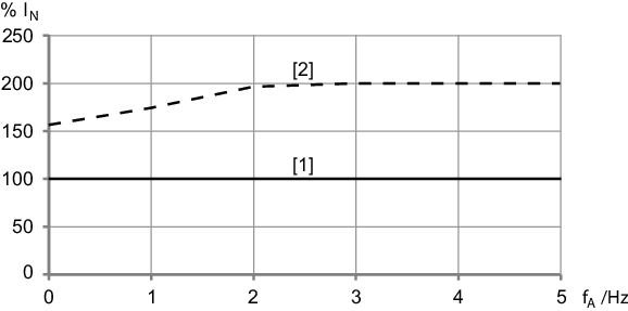
[1] | Continuous output current Icont at the smallest possible PWM frequency |
[2] | Temporally limited overload currentConfigure the overload current in the SEW Workbench. |
Observe the overload capacity of the device according to chapter Output.