Setting the address via the AS-Interface handheld programmer
INFORMATION

The inverter must be supplied with line voltage and/or DC 24 V backup voltage in order for the address to be set.
The AS-Interface handheld programmer offers the following functions:
- Reading and changing a device address
- Reading the device profile
- Reading and changing the data bits and parameter bits
- Functional test and test run
The handheld programmer is connected to the inverter via AS-Interface plug connector X4271 using a 2-wire connection cable.
The following table shows information about this connection:
Function | ||
Connection of AS-Interface data line | ||
Connection type | ||
M12, 4‑pin, male, A‑coded | ||
Connection diagram | ||
Assignment | ||
No. | Name | Function |
1 | AS+ | AS-Interface data line (+) |
2 | n.c. | Not assigned |
3 | AS− | AS-Interface data line (-) |
4 | n.c. | Not assigned |

Proceed as follows:
- The inverter is in an inhibited state.
- The inverter is supplied with line voltage and/or DC 24 V backup voltage.
- Disconnect the inverter from the AS‑Interface network.
- Connect the handheld programmer to the AS-Interface connection of the inverter and set the desired address.
- After addressing, reintegrate the inverter into the AS-Interface network.
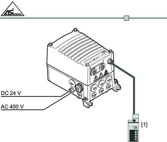
[1] | AS-Interface handheld programmer |
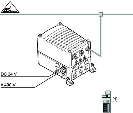
[1] | AS-Interface handheld programmer |
