Process data assignment
The Easy mode and Expert mode are available for the startup procedure of an SEW‑EURODRIVE inverter.
For information on the 2 parameter modes, refer to chapter Parameter setting modes of the inverter.
The Easy mode is only available up to firmware version < 11.
The cyclically transmitted data bits and the acyclically transmitted parameter bits are mapped to the process data structure of the inverter by the AS-Interface communication option.
Alternatively, SEW‑EURODRIVE also offers various MOVIKIT® software modules for extended functions. For information on the MOVIKIT® software module, refer to chapter Control with the MOVIKIT® software module.
The following table shows the process data assignment in the inverter:
AS-Interface data | Data processing in the inverter | ||
|---|---|---|---|
Process data buffer | Function | ||
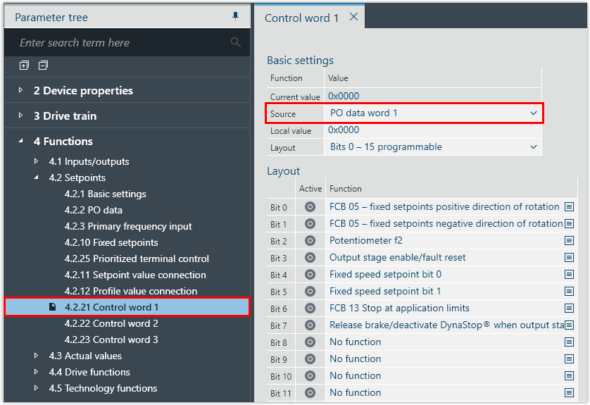
Cyclic data bits | DO (bit 0 – 7) | PO 1 (bit 0 – 7) | Control word 1Setting in delivery state or in Easy mode. If a MOVIKIT® software module is used, the assignment is adapted to the software module. For further information, refer to the documentation of the software module. |
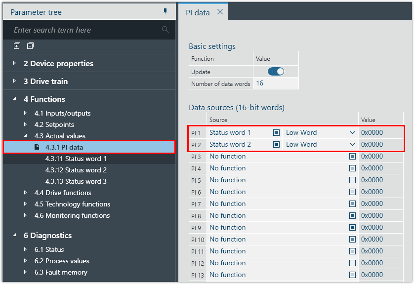
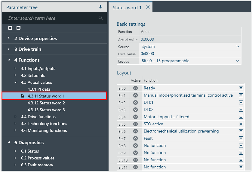
DI (bit 0 – 7) | PI 1 (bit 0 – 7) | Status word 1Setting in delivery state or in Easy mode. If a MOVIKIT® software module is used, the assignment is adapted to the software module. For further information, refer to the documentation of the software module. | |
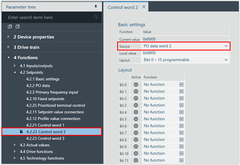
Acyclic | PO (bit 0 – 3) | PO 2 (bit 0 – 3) | Control word 2Setting in delivery state or in Easy mode. If a MOVIKIT® software module is used, the assignment is adapted to the software module. For further information, refer to the documentation of the software module. |
PI (bit 0 – 3) | PI 2 (bit 0 – 3) | Status word 2Setting in delivery state or in Easy mode. If a MOVIKIT® software module is used, the assignment is adapted to the software module. For further information, refer to the documentation of the software module. | |
For information regarding the predefined binary operating principle of the control bits and status bits, refer to chapter Process data configuration.
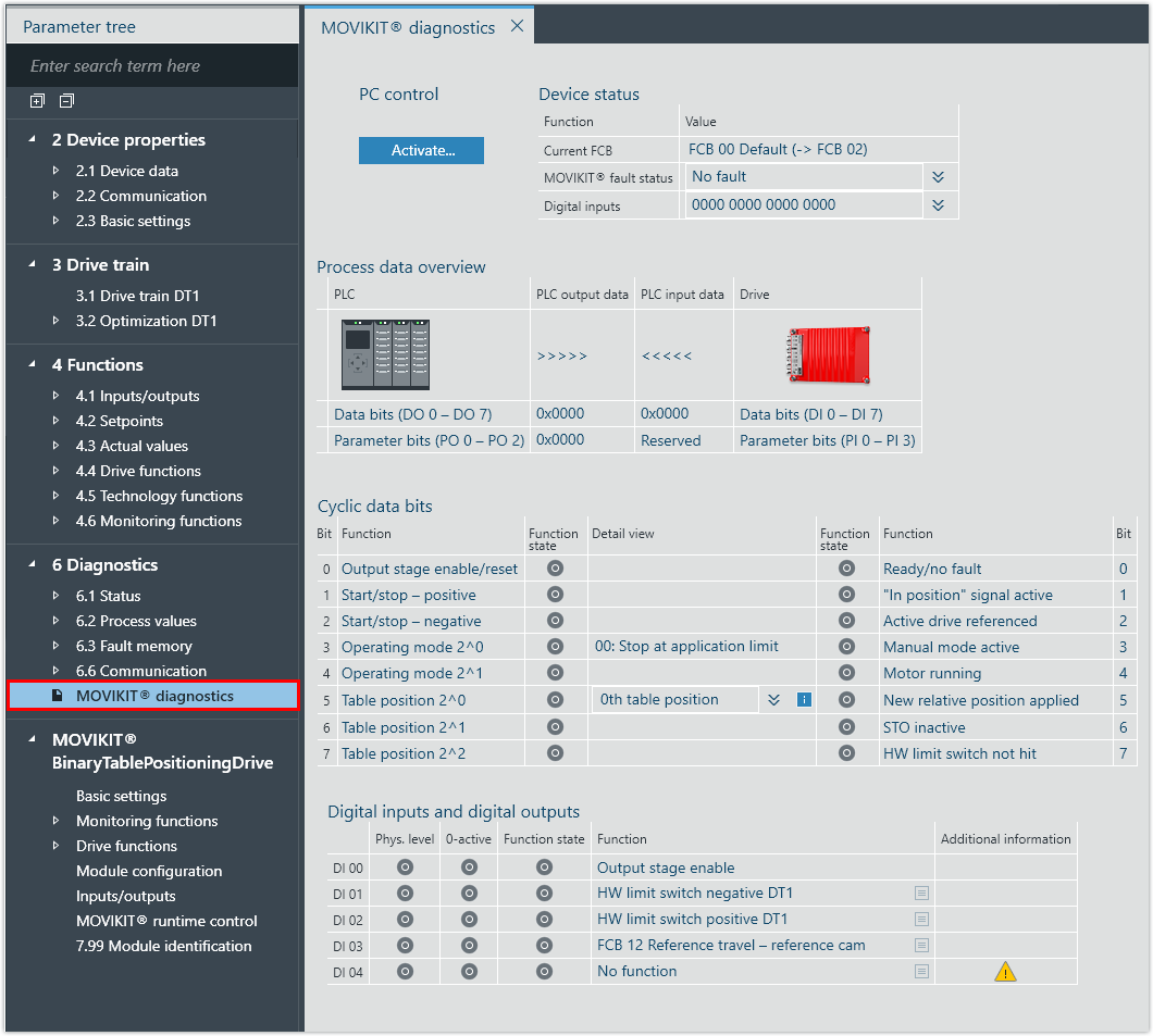
The following figures show the default settings in the MOVISUITE® engineering software. Only change this assignment if it is necessary for the application.
The acyclic serially transmitted data bytes of a double device's B device are not mapped to the process data structure of the inverter. This data is evaluated directly by the parameter structure of the inverter.
The correct transmission of data can be checked via:
- the response message of the CTT2 service used
- the corresponding parameter in MOVISUITE® or in the CBG21A keypad