Connecting the MOVI‑C® CONTROLLER to a Modbus TCP network
The following device topology is used in the example:
- Higher-level Modbus TCP master
- MOVIDRIVE® modular application inverter, MDD90A double-axis module
- MOVIDRIVE® modular application inverter, MDA90A single-axis module
The following figure is a schematic representation of the device topology:
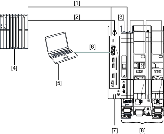
[1] | DC 24 V supply voltage |
[2] | Connection to Modbus TCP |
[3] | EtherCAT®/SBusPLUS connection |
[4] | Modbus TCP master |
[5] | Engineering PC |
[6] | Connection to engineering interface X80 |
[7] | MOVI-C® CONTROLLER progressive UHX65A-R |
[8] | MOVIDRIVE® modular axis system |
For configuration and startup of the devices, the following tools are used:
- MOVISUITE® for the devices of the MOVI‑C® modular automation system from SEW‑EURODRIVE
- MOVISUITE® contains the IEC Editor tool for programming the MOVI‑C® CONTROLLER.
- Higher-level Modbus TCP master for the PLC.
The MOVI‑C® CONTROLLER is integrated into the Modbus TCP network in several process steps:
- Configuration of the EtherCAT®/SBusPLUS stations
- Integrate the higher-level Modbus TCP master into the Modbus TCP network
- Checking the process data transfer
