Configuring subordinate nodes

WARNING

Unforeseen movements of the robot by configuring a jerk limitation on the inverters.
Physical injury and death.
- Make sure that no jerk limitation is configured on the inverters.
INFORMATION

For detailed information on how to configure the individual nodes, refer to the corresponding documentation.
Observe the following notes for software modules of lower-level nodes:
- The following axis group members may be used under the robot:
- MOVIDRIVE® with MOVIKIT® MultiMotion (recommended) or MOVIKIT® MulitMotion Camming (if the axis is to be controlled in the meantime via the "camming" operating mode)
- MOVI-C® virtual axis with MOVIKIT® MultiMotion or MOVIKIT® MulitMotion Camming (if the axis is to be controlled in the meantime via the "camming" operating mode)
- MOVI-C® SoftwareNode with MOVIKIT® MultiAxisController
- The software and hardware limit switches must be set before optimizing the drive train.
For the correct operation of the software module, at least the following startup steps are necessary for the lower-level nodes. Refer to the respective documentation for more information.
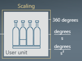
- Configure the drive train and define the user unit. See chapter Default units. The "User unit" component must be used in the drive train to ensure that the decimal places are set correctly.
- The kinematic models indicate whether linear or rotary axes must be configured. The linear axes of a Cartesian gantry, for example, must be configured as linear axes in the drive train. However, the axes of a roller gantry driving the circulating belt must be configured as rotary axes in the drive train. Also the pitch and the number of teeth must be set in the kinematic configuration
- Depending on the mechanical installation of the respective drive, a direction of rotation reversal must be set in the "Controller" parameter group. The positive direction of movement can be seen on the display in the 3D simulation. The procedure is described in chapter Referencing axes and performing function test.
- Insert the MOVIKIT® MultiMotion software module or MOVIKIT® MultiAxisController and use the basic setting for the decimal places.
- Activate the existing hardware limit switches (optional).
- Activate and configure the software limit switches (the software limit switches should be selected in such a way that they are located in the work envelope in front of the hardware limit switches in a distance that corresponds to the braking distance).
- Configure the reference travel.
- Configure the emergency stop ramps. Set the jerk to "0".
- Configure the torque limit.
- Optimize the "controller".
- Ensure that the "Modulo minimum" and "Modulo maximum" cycle monitoring is set to "0.0".

INFORMATION

The maximum possible position of an axis in user units (mm or ° for MOVIKIT® Robotics) is limited. The permitted range depends on the set decimal places of the position. This setting is made in the drive train or the drive functions of MOVIKIT® MultiMotion when parameterizing the resolution.
[ -2.147.483.648 / 10NumberOfDecimalPlaces, +2.147.483.647 / 10NumberOfDecimalPlaces ]
Exceeding these limits will result in an error. The limits result from the internal use of 32‑bit variables.
Example: Maximum travel range in user units when setting 4 decimal places of the position: [ -2.147.483.648 / 10000, +2.147.483.647 / 10000 ] = [ -214.748, +214.748 ]
[ -2.147.483.648 / 10000, +2.147.483.647 / 10000 ] = [ -214.748, +214.748 ]
INFORMATION

