For an external Windows system
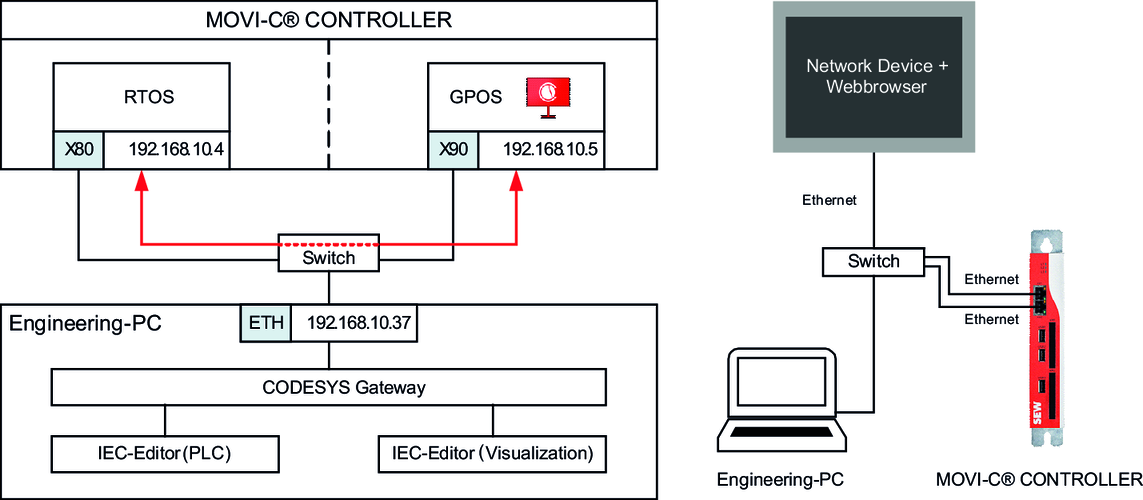
The network topology described here for setting up the visualization on an external Windows system uses a network switch as additional hardware to link the participants.
Data is exchanged between the IEC project and the visualization project via the physical network interfaces X80 and X90 of the MOVI-C® CONTROLLER and the network switch (red arrow in the graphic). The data source is thus configured for the use of the physical network interface X80. By default, the physical network interface X80 of the MOVI-C® CONTROLLER has the IP address 192.168.10.4 assigned to it. Access from the engineering PC to the Windows part of the MOVI-C® CONTROLLER (e.g. for loading the visualization project) is implemented via the physical network interface X90. By default, the physical network interface X90 of the MOVI-C® CONTROLLER has the IP address 192.168.10.5 assigned to it.
The symbol configuration of the IEC project is required so that the required variables will be available in the visualization project. The exported symbol file (.xml file) is stored in the configuration of the data source. See also Updating the symbol configuration, Exporting the symbol configuration and Updating variable information.
Step-by-step configuration of the data source
- A connection is active between the engineering PC (visualization project) and the IEC project for reading out the variables via the communication settings.
- Add data source manager (if not already available)
- Add a data source manager by right-clicking the application in the device tree of the IEC Editor and selecting the [Add Object] menu entry.
- Add data source
- Add a data source (data source type "CODESYS Symbolic") by right-clicking the Data Source Manager in the device tree of the IEC Editor and selecting the [Add Object] > [Data Source] menu item. The data source type corresponds to "CODESYS Symbolic". If necessary, the name of the data source can be adapted.
- Initialize data source
- Select the "From symbol file" option in the "Variable information" field and specify the file path of the symbol file previously exported from the IEC project. See also Exporting the symbol configuration.
- Define the IP address of the physical network interface X80 of the MOVI-C® CONTROLLER
(192.168.10.4). - Select option "CODESYS v3" in the "Connection type" field (no gateway support).
- Jump to the next configuration step with [Next].
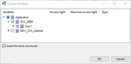
- Choose variables
- Select the variables that you wish to make available in the visualization project. The available variables are listed in the respective structure, and the required variables can be selected or deselected using check boxes (see example in screenshot).
- Finish data source configuration with [Finish]

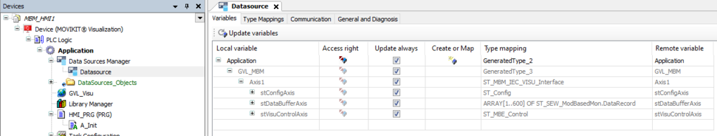
- The selected variables are available in the visualization project and can be linked to the visualization elements of the visualization views. All imported variables can be retrieved in the properties of the data source (double-click the data source) in the "Variables" tab. INFORMATION: Activate "Always update" to update the variables even if they are not used.