Checking safe communication
INFORMATION

The safety program in this example only serves to explain the test run of safety sub-functions and is not part of a safety program specified by SEW-EURODRIVE.
The safe process data cannot be controlled directly. This is why a safety program with the following functions must be created:
- Re-integrate the safe communication node that has been passivated by the safety sub-functions into the safe communication after fault acknowledgment.
- Deactivate the safety sub-functions. In deactivated safety operation only, certain troubleshooting measures of the safety program are switched off to enable changing the data of the safety program via watch tables.
Proceed as follows:
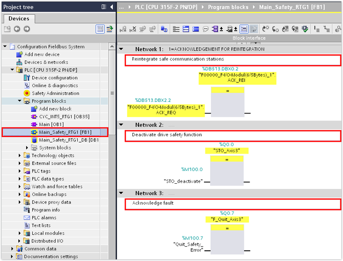
- In the TIA Portal project, select the main safety block
Main_Safety_RTG1 [FB1]. - Add the F-module with the following access functions to the safe communication node:
- Re-integrate the safe communication node: Use the variables
ACK_REQ(acknowledgment required for reintegration) andACK_REI(acknowledgment for reintegration) from the F‑periphery database. - Deactivate the safety sub-function: Assign a flag to the corresponding safe process output data word. A safe process output data word cannot be directly addressed. This is why the safe process output data word is switched by a flag (memory area to store temporary results).
- Acknowledge the error: Assign a flag to the corresponding safe process output data word.
- In the example, flags are assigned to the safe process output data 0.0 (safety sub-function STO) and 0.7 (fault acknowledgment).
- Compile the TIA Portal project and load the project into the safety controller.
- Establish an online connection between the safety controller and the safe communication node.
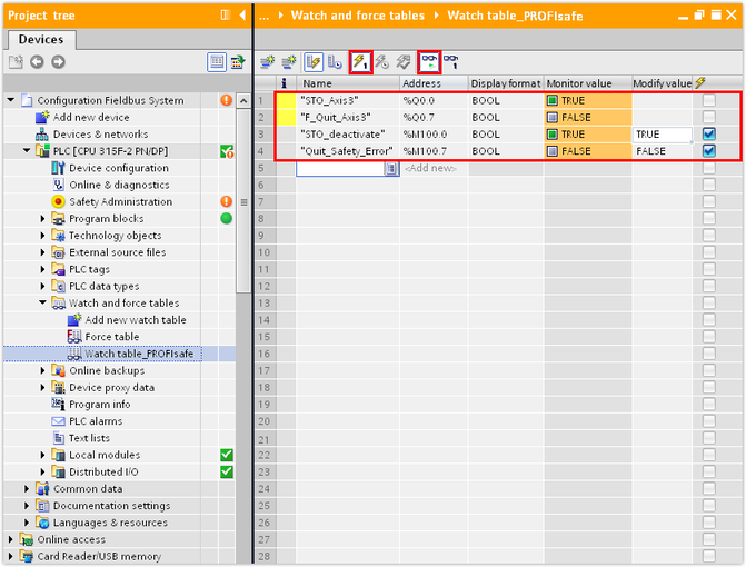
- Add a new watch table in the "Watch and force tables" subfolder of the safety controller.
- Add the safe process output data words referenced in the safety program and the assigned flags to the watch table.
- The drive is stopped by the STO safety sub-function and the safe communication node is passivated.
- Acknowledge the fault by setting the control value of the assigned flag to 1.
- Start the watching and controlling of the active variables.
- The safe communication node is integrated into the safe communication and the safety controller sends process data to the safe digital output of the communication node.
- Switch to the MOVISUITE® project and open the configuration of the safe communication node.
- In the diagnostics information of the safety protocol, check if the safety telegram (F-telegram) receives data.
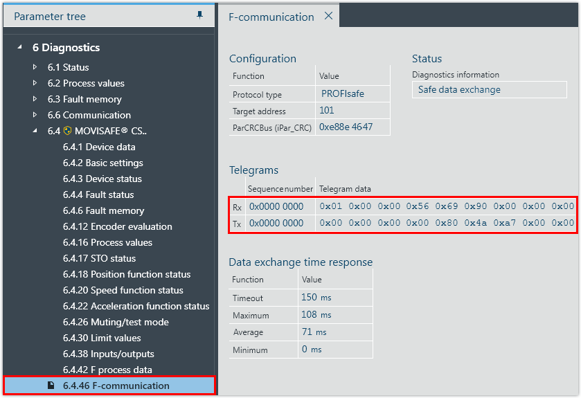
- If telegram data is received by the safe communication node, safe communication has been established successfully.
