Fieldbus communication diagnostics
INFORMATION

Diagnostics is shown as an example using the TIA Portal engineering tool.
Activate a variable table in the TIA Portal engineering tool and monitor the input and output range of the required axis. In the Variable Editor, you can monitor the inputs and outputs and control them, if necessary.
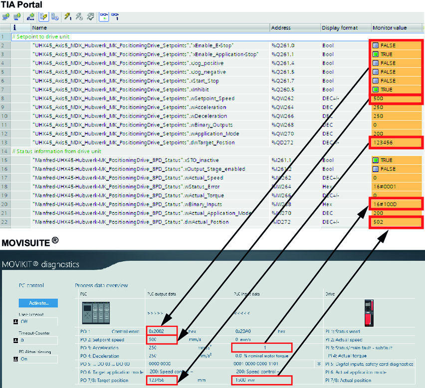
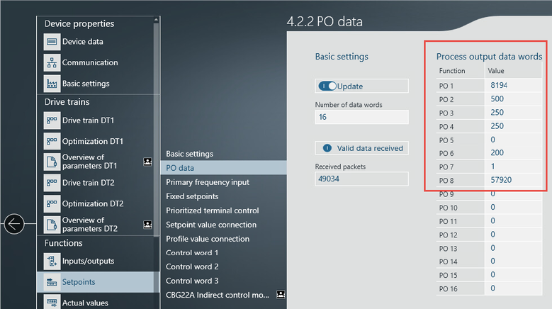
At the same time, you can view the incoming inverter data in MOVISUITE® under [Functions] > [Setpoints] > [PO data].
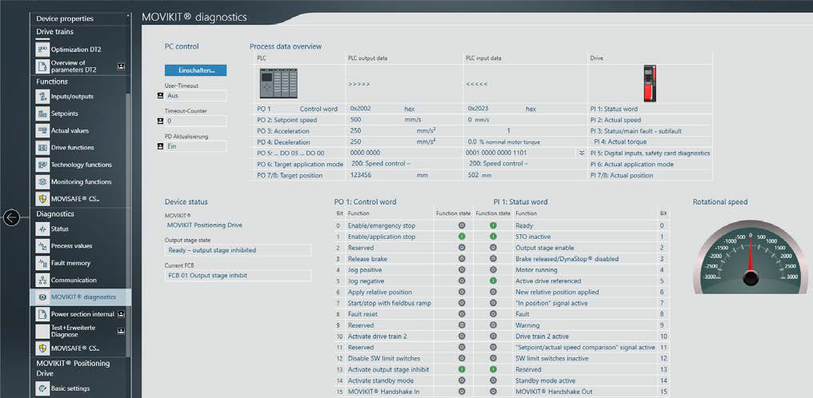
When using a MOVIKIT® software module of the "Drive" category, the process data is displayed under [Diagnostics] > [MOVIKIT® diagnostics] in a decoded format.