Generating a "Gateway Solution" application
Proceed as follows to generate a "Gateway Solution" application and load it onto the target device:
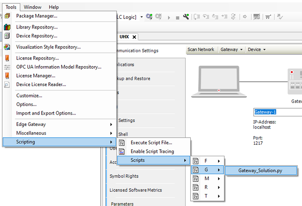
- Run the "Gateway Solution" script in the IEC Editor under [Tools] > [Scripting] > [Scripts] > [G].
The script performs the following functions automatically:
- Query for setting up web server-based visualization
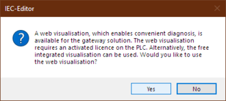
- The "Gateway Solution" application provides diagnostics of process data and gateway configuration via the integrated web server. It is therefore not mandatory to operate the IEC Editor. The following requirements must be met to use web diagnostics:
- The X80 engineering interface must be used.
- The required license for the MOVIKIT® Web Visualization software module (SMK1504-020, SMK1504-040 or SMK1504-060) must be available. If this license is not available, click the [No] button in the following dialog.
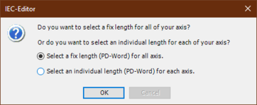
- Configuration of the number of process data between gateway and the individual inverters. To do this, you can configure a common process data length for all axes or individual process data lengths for the individual inverters.
- Extension of the IEC project by gateway IEC program code
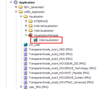
- Extension of the IEC project by the IEC program code for the MOVIKIT® Web Visualization software module.
- The corresponding objects and program parts are created automatically in the project tree of the IEC Editor as follows. The required program blocks are created for each individual axis.
- Compilation of the entire project
- Login for the target device
- Download of the application to the target device
- Creation of the "boot project" so that the application is saved to the target device in a power-failure proof manner.
- Start of the IEC application
- Completion of script execution with success message or error message when executing the actions
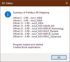
The "Gateway Solution" application is now completely configured and can be run on the controller. A possible EtherCAT® timeout (E32.02) or the display C3 (waiting for data) should no longer be displayed on the 7-segment display of the inverters.
