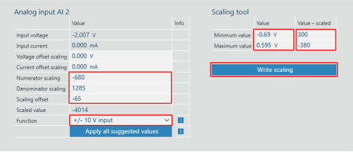
Adjust "Value – scaled"
- The drive train must be parameterized according to the configured mass moment of inertia.
- The strain gauge must be tarred to 0 V or 12 mA. If necessary, use a scaling offset).
- The brake on the lower drive is applied.
- Relieve the tension on the tower and note the actual position "center".
- Deflect the tower forwards and note the actual position and the analog value (depending on the "function" input voltage or input current).
- Deflect the tower backwards and note the actual position and the analog value (depending on the "function" input voltage or input current).
- Calculate the "Value – scaled" by multiplying the measured deflection (difference in actual positions) by a corresponding factor depending on the configured user units.
Example for user unit "1 mm" of the X-axis
Position | Actual position | Deflection | Factor | Value – scaled | Analog value |
|---|---|---|---|---|---|
"Center" | 87 | 0 |
| 0.0 | |
Deflection forwards | 57 | -30 | -10 | +300 | -0.69 |
Deflection backwards | 125 | +38 | -10 | -380 | 0.595 |
Example for user unit "0.1 mm" of the X-axis
Position | Actual position | Deflection | Factor | Value – scaled | Analog value |
|---|---|---|---|---|---|
"Center" | 87 | 0 |
| 0.0 | |
Deflection forwards | 57 | -30 | -100 | +3000 | -0.69 |
Deflection backwards | 125 | +38 | -100 | -3800 | 0.595 |
- Set the option [±-10 V input] or [4..20 mA] in the "Function" field in the "Analog input AI 2 (I/O card)" section of the "Additional function" configuration menu and click [Apply suggested values].
- In the "Scaling tool" area, enter the calculated values in the "Value – scaled" column.
- In the "Scaling tool" area, enter the recorded analog values (depending on the "Function" input voltage or input current) in the "Value" column.
- Click the [Write scaling] button.
- The values "Scaling numerator", "Scaling denominator" and "Scaling offset" in the "Analog input AI2" area are filled in automatically.