Insulation resistance test of a single DSK module
Preparation:
- Disconnect the DC link connections to the adjacent modules (DSK+ and DSK-).
- Unscrew all signal monitoring cables.
- Short-circuit the DSK module that you want to test between DSK+ and DSK-.
- Perform the insulation resistance test properly and record the measurement result in Test protocol for service work on the ESS.
- Select the largest possible value of the test device used.
- Test voltage = at least 500 VDC; ideally up to 2 kVDC
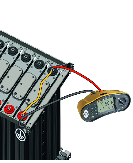
Measuring points | |
|---|---|
DSK+/- | PE connection mounting rail |
The insulation resistance test is considered as passed if a resistance value of ≥ 10 MOhm or no conductive connection is displayed at a test voltage of 500 V.
Several defective energy modules can also be present in a storage bundle. Replace them.
End the insulation resistance test:
- Remove the short circuit between DSK+ and DSK-.
- Restore the DC link connections between the individual DSK modules. Observe the tightening torques specified in the following table:
Connection point | Thread | Tightening torque |
|---|---|---|
DSK+ | M8 | 20 Nm |
DSK- | M10 | 30 Nm |
- Establish the DC link connection on the storage bundle (between DSK+ on module 1 and DSK- on module 8). Observe the correct sequence of the cables and the tightening torques from the following table:
Sequence of the cables | |
|---|---|
1 | Connection pole |
2 | Storage unit connection 35 mm² |
3 | Discharge unit connection 2.5 mm² |
4 | Washer |
5 | Lock washer |
6 | Screw |
Connection point | Thread | Tightening torque |
|---|---|---|
DSK+ | M8 | 20 Nm |
DSK- | M10 | 30 Nm |
- Screw on all signal monitoring cables.
