Position of motor terminal box and cable entry
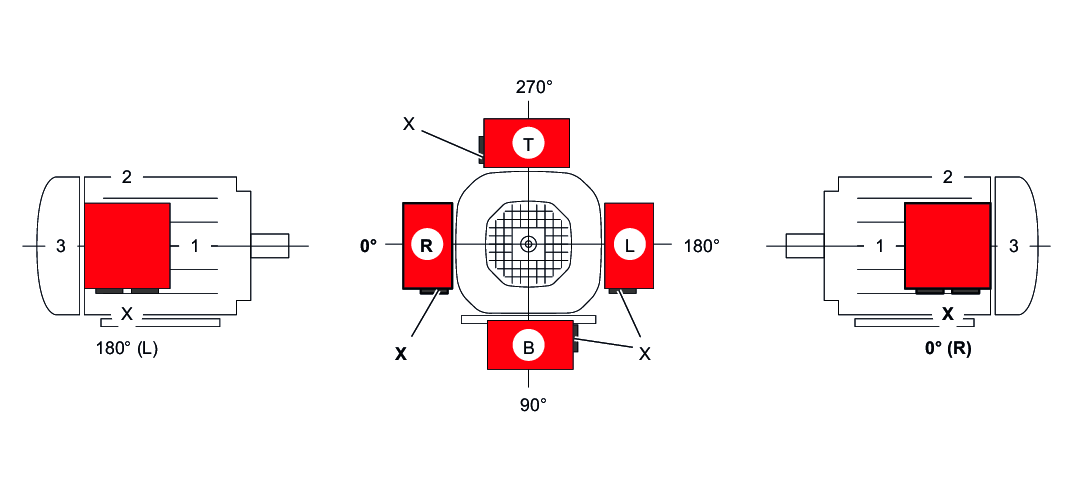
The position of the motor terminal box has so far been indicated with 0°, 90°, 180° or 270° as viewed onto the fan guard (B-side), see the following figure. A change to DIN EN 60034-1 stipulates that the following designation has to be used for the terminal box position of foot-mounted motors in the future:
- View of the output shaft = A-side
- Designation as R (right), B (bottom), L (left), and T (top)
This new designation applies to foot-mounted motors without a gear unit in mounting position B3 (= M1). For gearmotors, the previous designation is retained and is still specified with 0°, 90°, 180°, and 270° when looking at the fan guard = B-side. The following figure shows both designations. If the mounting position of the motor changes, R, B, L, and T are rotated accordingly. For motor mounting position B8 (= M3), T is at the bottom.
The position of the cable bushing can also be selected. "X" (= normal position), "1", "2" or "3" are possible, as shown in the following figure.
Without special information on the terminal box, the 0° version is supplied with cable bushing "X". For mounting position M3, SEW-EURODRIVE recommends selecting cable bushing "2".
For motor sizes 56 and 63, only cable entries "X" and "2" are possible. Exception: This restriction does not apply with IS connector.
With terminal box position 90° (B), check whether the gearmotor must be supported.
The position of the terminal box is not given on the nameplate.
