Dimension drawing of the MMF1. design connectors
The following figure shows an example of the additional dimensions of the optional connectors for a possible connector configuration.
For more information, refer to chapter "Electrical installation" > "Connector" > "Connector positions ...".
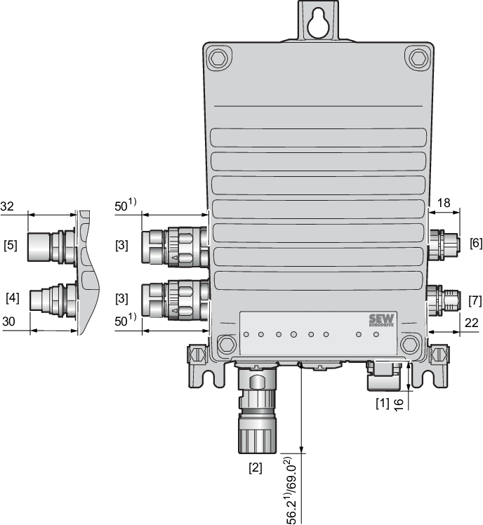
1) | Connector design M23 "Straight" |
2) | Connector design M23 "Angled" |
[1] | Optional pressure compensation |
[2] | Connector design M23, with union nut, female |
[3] | Connector design M23, without union nut, female |
[4] | Connector design M15-X-Power, without union nut, male |
[5] | Connector design M15-X-Power, with union nut, female |
[6] | Connector design M12, female |
[7] | Connector design M12, male |
All dimensions in mm.
