Connector including mating connector
The following figure shows the installation height including mating connector and bending radii of the customer-side connectors in conjunction with prefabricated cables.
For more information, refer to the product manual > chapter "Electrical installation" > Connectors".
INFORMATION

The dimensions of the mating connector are examples. Deviations are possible depending on the manufacturer.
The following table shows the total height for the different drive units. Allow for a minimum installation clearance so that installation of the connectors is guaranteed
Gearmotor | Xh in mm |
|---|---|
DCA63.. | 118 |
F.02DCA63.. | 199 |
F.03DCA63.. | 234 |
W.02DCA63.. | 132 |
W.03DCA63.. | 146 |
KNZ63DCA63.. | 118 |
PNZ63DCA63.. | 118 |
DCA80.. | 136 |
F.03DCA80.. | 234 |
W.03DCA80.. | 155 |
PNZ80DCA80.. | 136 |
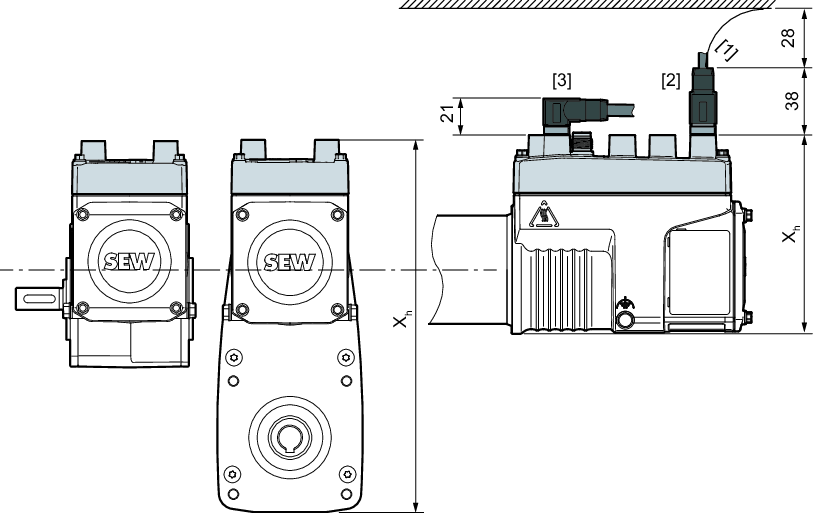
[1] | Bending radius |
[2] | "Straight" M12 connector design |
[3] | "Angled" M12 connector design |
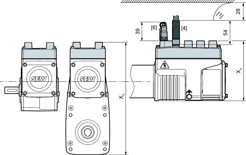
[4] | "Straight" M12 Power connector design |
[6] | STO jumper plug M12 |
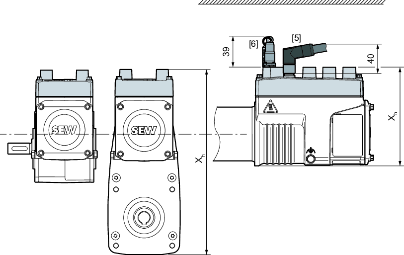
[5] | "Right-angle" M12 Power connector design |
[6] | STO jumper plug M12 |
